How To Recharge Freon In Car
Recharging your car's air conditioning system, specifically adding refrigerant (often incorrectly called "Freon," which is actually a brand name for R-12, now obsolete in most vehicles), can restore its cooling performance. This task requires a good understanding of the system's components and processes, along with careful execution. This guide provides detailed instructions suitable for experienced DIYers.
Understanding the Automotive AC System
Before diving into the recharge process, it's crucial to grasp the basic operation of your car's AC. The system works on the principle of heat transfer through refrigerant cycling.
Key Specs and Main Parts
The automotive AC system comprises several key components:
- Compressor: The heart of the system. It compresses the low-pressure, low-temperature refrigerant gas into a high-pressure, high-temperature gas. It's driven by a belt connected to the engine.
- Condenser: A radiator-like component located in front of the engine's radiator. The high-pressure, high-temperature refrigerant gas is cooled and condensed into a high-pressure liquid.
- Receiver-Drier (or Accumulator): Filters debris and removes moisture from the refrigerant. The receiver-drier is typically found on the high-pressure side of the system (between the condenser and the expansion valve), while the accumulator is on the low-pressure side (between the evaporator and the compressor). The type depends on the system design.
- Expansion Valve (or Orifice Tube): Meters the flow of high-pressure liquid refrigerant into the evaporator, causing a pressure drop and allowing the refrigerant to expand and vaporize. The expansion valve is usually more sophisticated and provides better control than the simple orifice tube.
- Evaporator: Located inside the passenger compartment, usually behind the dashboard. The low-pressure, low-temperature liquid refrigerant absorbs heat from the air passing over it, cooling the air before it enters the cabin. The refrigerant then turns into a low-pressure, low-temperature gas.
- Refrigerant Lines: Hoses and pipes that connect all the components and carry the refrigerant throughout the system.
- Service Ports (High and Low Side): Fittings that allow access to the system for servicing, including recharging. They have different sizes to prevent accidental connection.
Symbols and Conventions
When reviewing an AC system diagram (which you can download from us at the end of this article), you will encounter specific symbols. Here's a breakdown:
- Solid Lines: Represent refrigerant lines. The thickness of the line may indicate the size of the pipe or hose.
- Dotted Lines: Often represent electrical wiring or vacuum lines associated with the AC system's control mechanisms.
- Color Coding: While not universal, color coding can be used to distinguish between high-pressure and low-pressure lines. For example, red might indicate high-pressure and blue might indicate low-pressure.
- Component Symbols: Each component has a specific schematic symbol. You'll find rectangles for condensers and evaporators, circles for compressors, and various other symbols for valves, sensors, and switches. Refer to the diagram's key or legend for specific symbol definitions.
- Arrows: Indicate the direction of refrigerant flow.
How It Works: The Refrigeration Cycle
The refrigerant cycle is a closed-loop process:
- The compressor draws in low-pressure, low-temperature refrigerant gas and compresses it, increasing its pressure and temperature.
- The high-pressure, high-temperature gas flows to the condenser, where it releases heat to the outside air, causing it to condense into a high-pressure liquid.
- The high-pressure liquid flows through the receiver-drier (or accumulator), where moisture and debris are removed.
- The high-pressure liquid then flows through the expansion valve (or orifice tube), which meters the flow and reduces the pressure, causing the refrigerant to expand and vaporize into a low-pressure, low-temperature liquid.
- The low-pressure, low-temperature liquid flows into the evaporator, where it absorbs heat from the air passing over it, cooling the air. The refrigerant then turns back into a low-pressure, low-temperature gas.
- The low-pressure, low-temperature gas returns to the compressor, completing the cycle.
Recharging Procedure: A Step-by-Step Guide
Safety First! Always wear safety glasses and gloves when working with refrigerant. Refrigerant can cause frostbite and blindness. Work in a well-ventilated area.
- Gather Your Supplies: You'll need:
- Refrigerant (R-134a is the most common for modern vehicles). Check your vehicle's specification plate for the correct refrigerant type and quantity.
- Recharging kit with a pressure gauge.
- Gloves and safety glasses.
- A can tap (if not included in the kit).
- Manifold gauge set (optional, but highly recommended for accurate charging).
- Locate the Service Ports: Find the low-side and high-side service ports. The low-side port is typically located on the accumulator or the low-pressure line between the evaporator and the compressor. They are different sizes, so the recharge kit coupler will only fit the low-side port. Never force a fitting!
- Connect the Recharging Kit:
- Attach the can tap to the refrigerant can.
- Connect the hose from the can tap to the low-side service port.
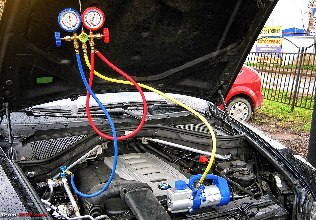
- Monitor the Pressure:
- Consult the pressure chart included with your recharging kit. The ideal pressure depends on the ambient temperature.
- Start the engine and turn on the AC to the maximum setting.
- Read the pressure gauge. If the pressure is low (below the recommended range for the ambient temperature), you need to add refrigerant.
- Add Refrigerant:
- Slowly release refrigerant into the system by opening the valve on the can tap.
- Monitor the pressure gauge closely. Avoid overcharging, as this can damage the system.
- Periodically shake the refrigerant can to ensure it empties completely.
- Repeat the process with additional cans if necessary, until the pressure reaches the recommended range.
- Disconnect and Test:
- Once the pressure is within the correct range, close the valve on the can tap and disconnect the recharging kit.
- Check the temperature of the air coming from the vents. It should be noticeably cooler.
Real-World Use: Troubleshooting Tips
- No Cold Air: If the system is completely empty, there may be a leak. Adding refrigerant without fixing the leak is a temporary solution. Consider adding leak detection dye to help locate the source of the leak.
- Compressor Not Engaging: If the compressor clutch is not engaging, the system might be too low on refrigerant. The low-pressure switch prevents the compressor from running to protect it from damage. Adding a small amount of refrigerant might be enough to engage the compressor. However, a faulty low-pressure switch or compressor clutch could also be the problem.
- Overcharging: Overcharging can damage the compressor and other components. If you suspect overcharging, have the system professionally evacuated and recharged with the correct amount of refrigerant. Symptoms include high pressure readings and poor cooling performance.
- Moisture in the System: Moisture can cause corrosion and reduce the system's efficiency. If the system has been open to the atmosphere for an extended period, have it professionally vacuumed to remove moisture before recharging.
- Inaccurate Pressure Readings: A faulty pressure gauge can lead to incorrect charging. Use a reliable gauge and double-check the readings.
Safety Considerations
The AC system contains high-pressure refrigerant, and improper handling can be dangerous:
- Refrigerant Burns: Refrigerant can cause severe frostbite if it comes into contact with skin or eyes. Always wear safety glasses and gloves.
- High Pressure: The system operates under high pressure. Never disconnect hoses or fittings while the system is pressurized.
- Environmental Impact: Refrigerant is harmful to the environment. Dispose of used refrigerant properly according to local regulations. Never vent refrigerant into the atmosphere.
- Compressor Safety: The compressor uses a clutch to engage and disengage. Do not disable or modify this clutch as it could damage the system.
File Download
For a detailed diagram of a typical automotive AC system, including component locations and refrigerant flow paths, you can download the file here. This diagram will be invaluable for understanding the system's layout and troubleshooting potential problems.