How To Remote Start A Nissan
So, you're looking to understand how to remote start your Nissan? Excellent! Whether you're troubleshooting a malfunctioning system, planning an aftermarket upgrade, or simply curious about the inner workings of your vehicle, knowing the ins and outs of the remote start system is invaluable. This deep dive will provide you with a technical understanding of the system, allowing you to diagnose issues, perform modifications (where appropriate), and gain a greater appreciation for your Nissan's technology.
Purpose of Understanding the Remote Start Diagram
Why bother with the nitty-gritty details? Well, a detailed understanding of the remote start system serves several critical purposes:
- Troubleshooting: When your remote start stops working, a schematic diagram can guide you to the problem area. Instead of blindly replacing parts, you can test specific circuits and components.
- Aftermarket Integration: Planning to install a new alarm system or a more advanced remote start module? Knowing the existing wiring and system architecture is crucial to avoid conflicts and ensure proper integration.
- Preventative Maintenance: Understanding how the system works allows you to anticipate potential problems and perform preventative maintenance, extending the life of your remote start and related components.
- Personal Knowledge: Simply put, it's cool to know how your car functions! Gaining this knowledge empowers you to be a more informed car owner and DIYer.
Key Specs and Main Parts of the Nissan Remote Start System
The specific components and wiring configurations will vary depending on the Nissan model and year, but the core elements remain largely the same. Here's a breakdown of the main parts:
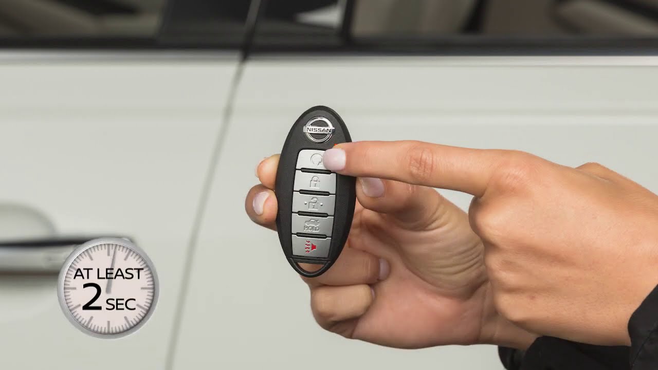
- Remote Start Transmitter (Key Fob): This is your handheld device that sends the remote start signal. It transmits a radio frequency (RF) signal to the vehicle.
- Remote Start Receiver/Module: This module, typically located under the dashboard, receives the RF signal from the key fob and initiates the start sequence. This module often contains the system's brain - a microprocessor that interprets the signal and controls other car systems.
- Hood Switch: A safety switch located under the hood. If the hood is open, the remote start system is disabled to prevent accidental starts during maintenance. This is a crucial safety feature.
- Brake Switch: Another safety switch located on the brake pedal assembly. Pressing the brake pedal while the engine is running under remote start mode typically disengages the system.
- Immobilizer Interface: This interface bypasses the vehicle's immobilizer system during remote start. The immobilizer prevents unauthorized starting of the engine without the correct key. The interface temporarily "fools" the immobilizer into thinking the key is present.
- Ignition Switch Wiring: The remote start system connects directly to the ignition switch wiring. This allows it to mimic the action of turning the key, engaging the starter motor, and energizing the necessary circuits.
- Parking Light Circuit: Often, the parking lights will flash to indicate successful remote start. The remote start module controls this circuit.
- HVAC Integration (Optional): Some systems integrate with the vehicle's heating, ventilation, and air conditioning (HVAC) system, allowing you to pre-heat or pre-cool the cabin.
Understanding the Schematic Diagram: Symbols and Conventions
Schematic diagrams use standardized symbols to represent electrical components and connections. Here's a guide to interpreting common symbols you'll encounter in a Nissan remote start diagram:
- Wires: Solid lines represent wires. Different colors indicate different circuits or functions (e.g., red for power, black for ground, etc.). The thickness of a line usually doesn't represent wire gauge, but it's good to verify the diagram's legend.
- Ground: Typically represented by a series of horizontal lines, often resembling an upside-down pyramid or a triangle pointing down. It signifies a connection to the vehicle's chassis ground.
- Resistors: Shown as a zig-zag line or a rectangle. Resistors limit current flow.
- Capacitors: Represented by two parallel lines. Capacitors store electrical energy.
- Diodes: A triangle pointing to a vertical line. Diodes allow current to flow in only one direction.
- Relays: A coil symbol connected to a switch. Relays use a small current to control a larger current circuit. They are often used in remote start systems to control high-current functions like engaging the starter motor.
- Switches: A line with a hinged connector. Indicates a physical switch that opens or closes a circuit.
- Connectors: Represented by circles or squares where wires join. Important for identifying connection points when troubleshooting.
- Modules: Often represented by rectangles with pin numbers indicated. The pins specify where wires connect to the module.
Color Codes: Wire colors are crucial for identification. Common colors include:
- B - Black (Ground)
- R - Red (Power)
- W - White
- BL - Blue
- GR - Green
- Y - Yellow
- OR - Orange
- P - Pink
- L - Light Blue
Always refer to the diagram's legend for specific color code definitions, as they can vary slightly between models.
How the Nissan Remote Start System Works
The remote start system operates in a series of steps:
- Signal Transmission: You press the remote start button on the key fob. The fob transmits an encoded RF signal.
- Signal Reception: The remote start receiver/module in the vehicle receives and decodes the RF signal.
- System Verification: The module checks safety interlocks, such as the hood switch and brake switch. If these are active (e.g., hood is open), the system will not proceed.
- Immobilizer Bypass: The immobilizer interface temporarily bypasses the vehicle's immobilizer system. This is a critical step, as it allows the engine to start without the physical key present.
- Ignition Sequence: The module mimics the action of turning the key. It activates the appropriate circuits in the ignition switch wiring, including powering up the necessary sensors and actuators.
- Starter Engagement: The module engages the starter motor until the engine starts.
- Engine Running Verification: The module monitors engine RPM to ensure the engine is running successfully.
- Parking Light Activation: The parking lights flash to indicate successful remote start.
- System Shutdown: The engine will run for a pre-determined time (typically 10-15 minutes) or until the brake pedal is pressed, or the remote start button is pressed again.
Real-World Use: Basic Troubleshooting Tips
Here are a few common problems and troubleshooting tips:
- Remote start doesn't work at all: Check the key fob battery. Also check fuses related to the remote start system. Consult your vehicle's owner's manual for fuse locations.
- Remote start cranks but doesn't start: This could indicate a problem with the immobilizer bypass or a fuel delivery issue.
- Remote start starts but shuts off immediately: Check the hood switch. It might be faulty or misaligned.
- Parking lights don't flash: Check the parking light fuse and the wiring to the parking light circuit.
Always use a multimeter to test circuits before replacing components. A wiring diagram will help you pinpoint the test points.
Safety Precautions
Working with automotive electrical systems can be dangerous. Here are some essential safety precautions:
- Disconnect the Battery: Always disconnect the negative battery terminal before working on any electrical components. This prevents accidental shorts and potential electrical shocks.
- Avoid Working with Airbag Circuits: Airbag circuits contain highly sensitive and potentially dangerous components. Unless you are specifically trained in airbag system repair, avoid working near them.
- Use Proper Tools: Use insulated tools and a multimeter to test circuits safely.
- Consult a Professional: If you are not comfortable working with electrical systems, consult a qualified automotive technician.
- High Current Components: Be extremely careful around components like the starter solenoid and ignition switch wiring. These carry very high currents that can cause severe burns or electrical shock.
Remember, safety should always be your top priority.
We have the complete schematic diagram file for your Nissan's remote start system. This diagram provides a comprehensive overview of the system's wiring, components, and connections. Understanding this diagram will empower you to troubleshoot issues, perform modifications, and gain a deeper understanding of your vehicle. Download the file and use it as a valuable resource for your automotive endeavors. Remember to always exercise caution and consult a professional if you are unsure about any aspect of the repair or modification process. Good luck!