How To Remote Start Nissan Altima
Alright, let's dive into remote starting your Nissan Altima. This guide will walk you through understanding the system, its components, and troubleshooting common issues. Whether you're looking to diagnose a problem, perform repairs, or simply understand how this convenient feature works, this information will be invaluable. We've got the complete wiring diagram ready for you to download at the end of this article, making your task even easier. Let's get started!
Key Specs and Main Parts
The remote start system in a Nissan Altima isn't just one component; it's a network of interconnected modules and sensors working together. Understanding these parts is critical for any troubleshooting or modification. Here's a breakdown:
- Remote Key Fob: This is your primary interface. It transmits radio frequency (RF) signals to the vehicle's receiver to initiate the remote start sequence.
- RF Receiver Module: Located within the vehicle (usually near the immobilizer), this module receives the RF signal from the key fob and decodes the command.
- BCM (Body Control Module): The BCM is the central control unit for many of the Altima's electronic functions, including power windows, door locks, and, critically, the remote start system. It receives signals from the RF Receiver and initiates the starting sequence.
- ECM/PCM (Engine Control Module/Powertrain Control Module): The ECM (or PCM, which combines engine and transmission control) is the brain of the engine. It controls fuel injection, ignition timing, and other critical engine functions. The BCM communicates with the ECM/PCM to start the engine.
- Immobilizer System: A security feature designed to prevent unauthorized starting of the vehicle. It verifies that the correct key is present before allowing the engine to start. The remote start system must bypass or work in conjunction with the immobilizer.
- Hood Switch: This switch detects whether the hood is open. For safety reasons, the remote start system is disabled if the hood is open.
- Brake Switch: This switch detects whether the brake pedal is pressed. This is used, among other things, to disengage the remote start if the brake pedal is pressed before the key is inserted.
- Neutral Safety Switch (Automatic Transmissions Only): This switch ensures that the vehicle is in Park or Neutral before allowing the remote start system to engage.
Key specs to consider:
- Operating Frequency: The frequency at which the key fob transmits signals (e.g., 315 MHz or 433 MHz).
- Operating Voltage: The voltage required for each module to function correctly (typically 12V DC).
- Communication Protocol: The protocol used for communication between modules (e.g., CAN bus).
Symbols Explained
Understanding the wiring diagram depends on knowing the symbols. Here's a breakdown of common symbols you'll encounter:
- Solid Lines: Represent wires. Thicker lines usually indicate wires carrying higher current.
- Dashed Lines: Often represent shielded wires or communication lines like the CAN bus.
- Circles: Typically represent connectors. A circle with a number inside indicates a specific pin number within the connector.
- Squares: Usually represent components like modules, switches, or relays.
- Ground Symbol (⏚): Indicates a connection to the vehicle's chassis ground.
- Battery Symbol (+): Indicates a connection to the positive terminal of the battery.
- Resistor Symbol (zigzag line): Represents a resistor, which limits current flow.
- Capacitor Symbol (two parallel lines): Represents a capacitor, which stores electrical energy.
- Diode Symbol (triangle pointing to a line): Represents a diode, which allows current to flow in only one direction.
Color Coding: Wiring diagrams often use color-coded wires. Common colors include:
- Red: Typically indicates a power wire.
- Black: Typically indicates a ground wire.
- Blue, Green, Yellow, White: Often used for signal wires or control wires. Always refer to the diagram's legend for specific color meanings.
How It Works
The remote start process involves a carefully orchestrated sequence of events:
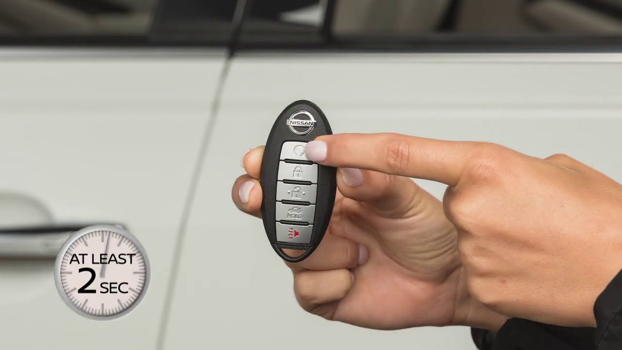
- Signal Transmission: You press the remote start button on the key fob. This sends an RF signal.
- Signal Reception: The RF Receiver Module in the Altima receives the signal.
- Authentication: The RF Receiver decodes the signal and sends a request to the BCM. The BCM verifies the signal is valid and checks security parameters (e.g., immobilizer status).
- Safety Checks: The BCM checks the status of safety switches like the hood switch, brake switch, and neutral safety switch. If any of these switches indicate an unsafe condition (e.g., hood open), the remote start sequence is aborted.
- Engine Start Sequence: If all checks pass, the BCM sends a signal to the ECM/PCM. The ECM/PCM then activates the starter motor and controls fuel injection and ignition to start the engine.
- Run Time: The engine typically runs for a pre-programmed duration (e.g., 10-15 minutes). If you want to extend the run time, you may need to press the remote start button again (depending on the vehicle's programming).
- Shutdown: The engine will shut down automatically after the pre-programmed run time expires, or if you press the remote start button again while the engine is running. It will also shut down if the brake pedal is pressed before the key is inserted.
Important Note: The immobilizer system is a critical part of this process. The remote start system must be programmed to bypass or work in conjunction with the immobilizer to allow the engine to start remotely. This often involves using a bypass module that temporarily deactivates the immobilizer during the remote start sequence.
Real-World Use – Basic Troubleshooting Tips
Here are some common issues and troubleshooting steps:
- Remote Start Not Working:
- Check the Key Fob Battery: This is the most common issue. Replace the battery with a fresh one.
- Check the Hood Switch: Make sure the hood is fully closed. Inspect the hood switch for damage or corrosion. Test the switch with a multimeter to ensure it's functioning correctly.
- Check Fuses: Locate the fuse(s) related to the remote start system (refer to your owner's manual) and check for blown fuses. Replace any blown fuses with the correct amperage.
- Check for Diagnostic Trouble Codes (DTCs): Use an OBD-II scanner to check for any DTCs related to the remote start system. These codes can provide valuable clues about the problem.
- Immobilizer Issues: If the immobilizer system is malfunctioning, it can prevent the remote start from working. Try starting the car with the key. If the key doesn't work, consult a qualified technician.
- Engine Starts and Immediately Shuts Off:
- Immobilizer Issue: This often indicates a problem with the immobilizer bypass module.
- Fuel Supply Issue: Check for fuel pump problems or clogged fuel filters.
- Sensor Malfunction: A faulty crankshaft position sensor or camshaft position sensor can cause the engine to stall shortly after starting.
- Limited Range:
- Key Fob Battery: A weak battery can reduce the range of the key fob.
- Antenna Obstruction: Make sure there are no obstructions blocking the signal between the key fob and the vehicle's receiver.
- Interference: Radio frequency interference from other devices can also reduce the range.
When troubleshooting, remember to always disconnect the negative battery terminal before working on any electrical components to prevent accidental shorts.
Safety – Highlight Risky Components
Working with automotive electrical systems involves inherent risks. Be especially cautious when dealing with the following:
- Airbag System: Never tamper with the airbag system wiring. Accidental deployment can cause serious injury.
- Immobilizer System: Incorrectly modifying the immobilizer system can disable your vehicle and potentially compromise its security.
- High-Current Wiring: Be careful when working with wires that carry high current (e.g., starter motor wiring). Short circuits can cause fires.
Crucial Reminder: If you're not comfortable working with automotive electrical systems, it's best to consult a qualified technician. Improper installation or repairs can damage your vehicle and potentially create a safety hazard.
We have the complete wiring diagram file ready for you. To download, please click here. This diagram will be an invaluable resource as you troubleshoot or learn more about your Nissan Altima's remote start system. Good luck, and stay safe!