How To Remote Start Nissan Sentra
So, you're looking to understand how the remote start system on your Nissan Sentra ticks? Maybe you're troubleshooting a flaky system, planning an upgrade, or simply satisfying your curiosity about automotive technology. This guide will walk you through the key aspects of the remote start system, using an example wiring diagram to illustrate the components and their interactions. Having a solid grasp of this system can save you money on repairs, empower you to perform your own modifications, and give you a deeper appreciation for the technology under the hood.
Purpose of Understanding the Wiring Diagram
Understanding the wiring diagram is crucial for several reasons. Firstly, it's your roadmap for troubleshooting. When the remote start isn't working, tracing the circuits helps pinpoint the faulty component. Secondly, if you're planning to add aftermarket components or modify the existing system, the diagram reveals how the system is wired and how to safely integrate new elements. Thirdly, it provides a solid base for diagnosing electrical issues with the immobilizer or other related systems. Finally, it's an invaluable learning tool for understanding modern automotive electrical systems.
Key Specs and Main Parts
The remote start system on a Nissan Sentra (specific year ranges may vary, so always refer to your vehicle's service manual) generally includes these key components:
- Remote Start Module: This is the brain of the system, receiving the signal from the key fob and initiating the starting sequence. It also communicates with the vehicle's immobilizer and security system.
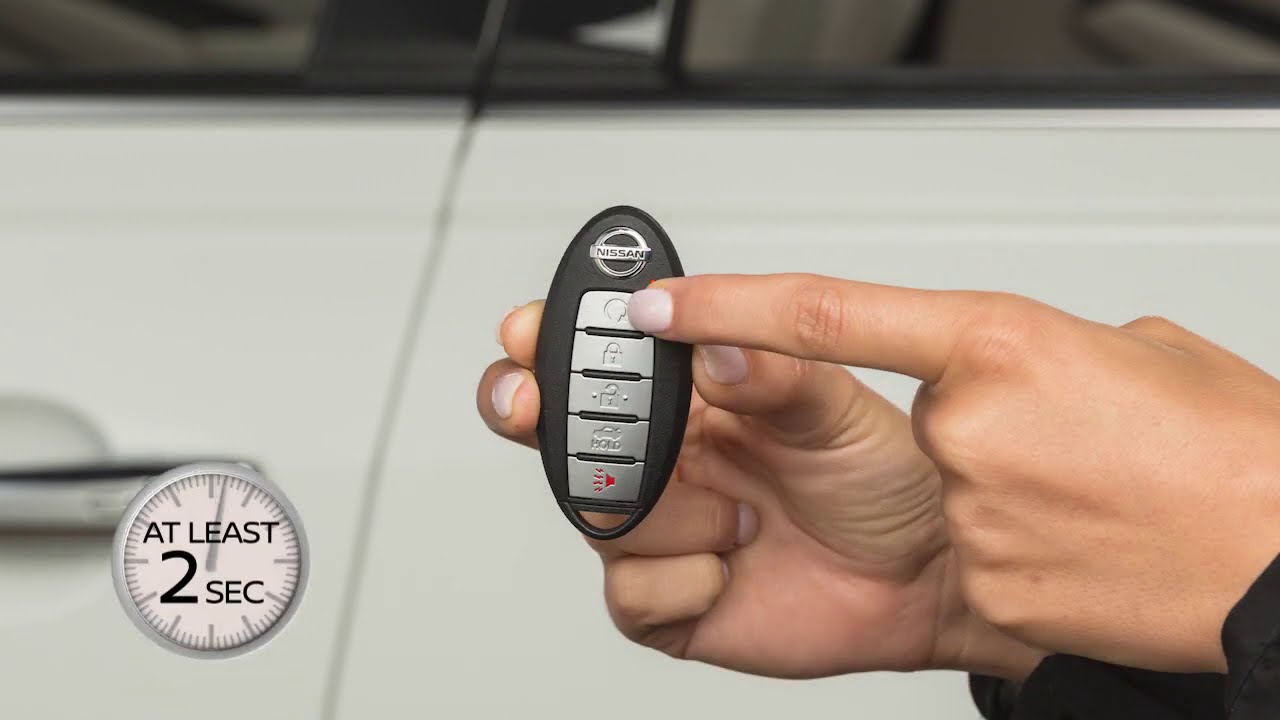
- Key Fob: The transmitter that sends the remote start command. It usually operates on a specific radio frequency (e.g., 433 MHz or 915 MHz).
- Hood Switch: A safety switch that prevents the remote start from engaging if the hood is open.
- Brake Switch: Another safety switch that disengages the remote start if the brake pedal is pressed.
- Ignition Switch Wiring: The harness connected to the ignition switch that provides the necessary signals to start the engine.
- Body Control Module (BCM): The BCM manages various electrical functions in the car, including the lights, door locks, and potentially the remote start integration. It acts as a gateway for various vehicle systems.
- Immobilizer System: Prevents theft by requiring a valid key to start the engine. The remote start system must bypass or work in conjunction with the immobilizer. This often involves transmitting a temporary RF signal.
- Antenna: Receives the signal from the key fob. Its placement affects range and reliability.
Key Specs to consider:
- Operating Voltage: Usually 12V DC (car battery voltage).
- Signal Frequency: The frequency used by the key fob for communication (e.g., 433 MHz).
- Current Draw: The amount of current the remote start module draws when idle and when active.
- Operating Temperature: The temperature range in which the system is designed to operate reliably.
Symbols – Decoding the Wiring Diagram
Understanding the symbols in the wiring diagram is essential for interpreting the information. Here's a breakdown of common symbols:
- Lines: Represent wires or conductors. Different line thicknesses may indicate wire gauge (thicker lines = thicker wires = can carry more current). Dashed lines often represent shielded cables or data lines (like CAN bus).
- Colors: Each wire is typically color-coded. The diagram will include a color code chart explaining what each color represents (e.g., BLU = Blue, RED = Red, GRN = Green, BLK = Black). These colors are crucial for identifying the correct wires during installation or troubleshooting.
- Circles or Squares with Letters/Numbers: Indicate connectors or terminal points. The letters/numbers are reference identifiers. You can find physical connectors inside of your Nissan Sentra using these identifiers.
- Rectangles: Typically represent components like relays, switches, or modules (e.g., the remote start module).
- Ground Symbol: Looks like an upside-down triangle or a series of decreasing horizontal lines. Indicates the connection point to the vehicle's chassis ground.
- Fuse Symbol: A zigzag line within a rectangle. Indicates a fuse that protects the circuit from overcurrent.
- Diode Symbol: A triangle pointing towards a vertical line. Diodes allow current to flow in one direction only.
Understanding the diagram requires grasping the flow of electricity. Follow the lines, identify the components, and understand how they interact with each other.
How It Works
The remote start process unfolds in the following steps:
- Key Fob Signal: You press the remote start button on the key fob. This sends a coded radio frequency (RF) signal to the antenna connected to the remote start module.
- Module Activation: The remote start module receives the signal and verifies its validity (e.g., checks for the correct security code).
- Safety Checks: The module checks the safety switches (hood switch and brake switch). If the hood is open or the brake pedal is pressed, the remote start sequence is aborted.
- Immobilizer Bypass: The module bypasses the vehicle's immobilizer system. This might involve transmitting a temporary RF signal that mimics a valid key, or using a data-based bypass through the CAN bus.
- Ignition Sequence: The module activates the ignition circuit, engaging the starter motor and initiating the engine starting process. This typically involves sending signals to the ignition switch wiring to simulate turning the key.
- Engine Running: Once the engine starts, the module monitors engine parameters (e.g., RPM, oil pressure) to ensure it's running properly.
- Shutdown: The engine will run for a predetermined time (e.g., 15 minutes) and then automatically shut off. You can also typically shut it down manually by pressing the remote start button again or by pressing the brake pedal.
Modern systems often use the CAN bus (Controller Area Network) for communication between the remote start module, BCM, and other vehicle systems. The CAN bus is a robust and efficient communication protocol that allows different electronic control units (ECUs) in the vehicle to share information.
Real-World Use – Basic Troubleshooting Tips
Here are some common remote start issues and troubleshooting steps:
- Remote Start Doesn't Work at All:
- Check the battery in the key fob.
- Check the fuses associated with the remote start system. Use a multimeter to test for continuity across the fuse.
- Ensure the hood is closed and the hood switch is functioning correctly.
- Check the brake switch. Make sure the brake lights are working.
- Inspect the antenna connection to the remote start module.
- Remote Start Works Intermittently:
- Check the antenna placement and ensure it's not obstructed.
- Check for loose wiring connections, especially at the remote start module and ignition switch.
- Inspect the battery voltage. A low battery can cause intermittent issues.
- Engine Starts But Immediately Shuts Off:
- This often indicates an immobilizer bypass issue. Check the immobilizer bypass module and its connections.
- Verify the engine RPM signal is being properly read by the remote start module.
Always use a multimeter to test voltages and continuity when troubleshooting electrical problems. A multimeter is your best friend in diagnosing these issues.
Safety – Risky Components
Working with automotive electrical systems involves inherent risks. Here are some critical safety considerations:
- Battery Disconnect: Always disconnect the negative battery terminal before working on any electrical components. This prevents accidental shorts and potential damage to the vehicle's electrical system.
- Airbag System: Be extremely cautious when working near the airbag system. Disconnecting or tampering with airbag wiring can cause accidental deployment. Consult the service manual for proper procedures.
- High-Current Circuits: The ignition circuit carries high current. Use caution when working with these wires to avoid electrical shock.
- Wiring Identification: Always double-check wire identification using the wiring diagram before making any connections. Incorrect wiring can damage the vehicle's electrical system.
- Soldering and Insulation: Use proper soldering techniques and ensure all connections are properly insulated to prevent shorts and corrosion.
It's wise to consult a professional if you're uncomfortable working with any of these components.
This detailed information and the wiring diagram should equip you with a good understanding of your Nissan Sentra's remote start system. With careful study and meticulous work, you can troubleshoot issues, plan upgrades, and expand your automotive knowledge.
We have the comprehensive wiring diagram file available for download to further assist you in your endeavors.