How To Set The Garage Door Opener
Alright, let's dive into the world of garage door openers. This isn't just about pushing a button and magically getting your car out of the rain; it's about understanding the intricate electromechanical system that makes it all happen. Understanding how to set your garage door opener, armed with the right information and a wiring diagram, empowers you to diagnose problems, perform basic maintenance, and even upgrade components safely.
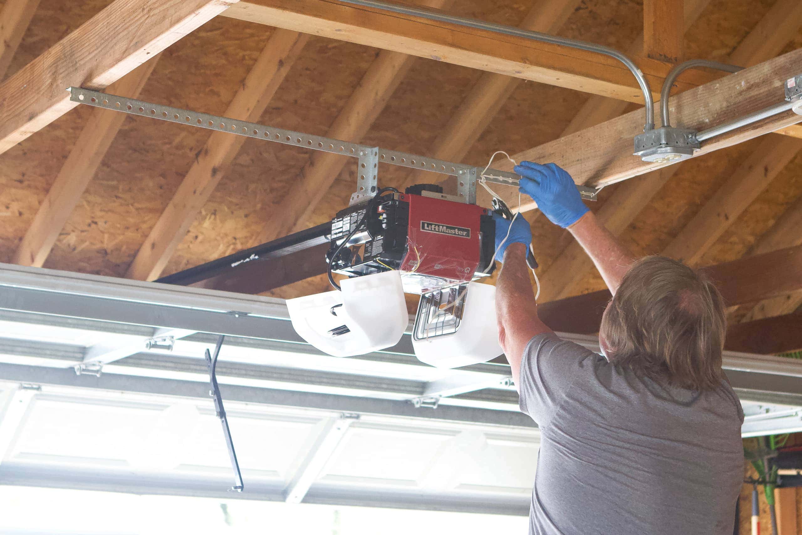
Why This Matters: Taking Control of Your Garage Door Opener
Having a solid understanding of your garage door opener – and especially having access to a detailed wiring diagram – opens doors (pun intended!) to several key benefits:
- Troubleshooting and Repair: When your garage door starts acting up – refusing to open, closing erratically, or making strange noises – the diagram is your first line of defense. You can trace circuits, identify faulty components, and potentially save a ton of money on service calls.
- DIY Upgrades and Modifications: Want to add smart home functionality? Or maybe replace a failing motor? The wiring diagram shows you exactly where to safely connect new components.
- Learning and Understanding: Even if your garage door is working perfectly, understanding the system gives you valuable insight into electromechanical devices in general. It’s a great way to expand your DIY skills and become more self-sufficient.
- Safety: A good understanding of the electrical components involved allows for a safer environment when working on the unit.
Key Specs and Main Parts of a Garage Door Opener
Before we get into the specifics of the wiring diagram, let's review the key components that make up a typical garage door opener:
- Motor: This is the heart of the system, providing the power to lift and lower the door. Motors are typically AC (Alternating Current) or DC (Direct Current), with DC motors offering smoother and quieter operation, often with battery backup.
- Drive System: This translates the motor's rotational motion into linear motion. Common types include:
- Chain Drive: The most common and generally the most affordable. Uses a chain to pull the door.
- Belt Drive: Quieter than chain drives, using a reinforced rubber belt.
- Screw Drive: Uses a threaded rod to move the door.
- Direct Drive: The motor is directly connected to the door, eliminating the need for a separate drive system.
- Limit Switches: These crucial components define the upper and lower limits of the door's travel. They tell the motor when to stop, preventing the door from over-traveling and potentially damaging itself or the surrounding structure. Limit switches can be mechanical (physical switches) or electronic (using sensors).
- Safety Sensors (Photo Eyes): These are critical safety devices. They emit an infrared beam across the door opening. If the beam is broken, the door will not close, preventing injury to people or pets.
- Control Board (Logic Board): This is the "brain" of the system. It receives signals from the remote, wall button, and safety sensors, and controls the motor accordingly.
- Transformer: Steps down the household voltage (typically 120V AC in North America) to a lower voltage (typically 12V or 24V AC/DC) for the control board and accessories.
- Capacitor: Used to provide the motor with the extra surge of power it needs to start.
Understanding Garage Door Opener Wiring Diagram Symbols
Wiring diagrams use a standardized set of symbols to represent components and connections. Here are some of the most common symbols you'll encounter:
- Solid Lines: Represent wires or conductors. The thickness of the line doesn't usually indicate wire gauge, but it can in some diagrams.
- Dashed Lines: Often represent shielded cables or less critical connections. Sometimes used for ground wires, though dedicated ground symbols are more common.
- Circles: Can represent various components depending on what's inside the circle. A circle with a resistor symbol inside represents a resistor, a circle with a capacitor represents a capacitor, and so on.
- Squares/Rectangles: Typically represent terminal blocks or connection points.
- Zig-zag Lines: Represent resistors.
- Parallel Lines: Represent capacitors.
- Coils: Represent inductors or transformers.
- Ground Symbol: Usually a series of horizontal lines decreasing in length, connected to a vertical line. Indicates a connection to ground (earth).
- Switch Symbols: Various symbols represent different types of switches (momentary, toggle, limit switch, etc.). Pay close attention to how the switch is wired - normally open (NO) or normally closed (NC).
- Motor Symbol: A circle with an "M" inside.
- Photo Eye Symbol: Usually a stylized representation of a light source and a sensor.
Color coding of wires is also important. Common colors include:
- Black: Usually indicates a hot (live) wire in AC circuits.
- White: Usually indicates a neutral wire in AC circuits.
- Green or Bare Wire: Ground wire.
- Red: Often used for control signals or low-voltage power.
How It Works: A Deep Dive into the Electromechanical Process
Here's a simplified breakdown of how a garage door opener typically works:
- Activation: You press the button on your remote or wall-mounted control. This sends a signal to the control board.
- Signal Processing: The control board interprets the signal and checks the status of the safety sensors. If the sensors are clear (beam is unbroken), the control board proceeds.
- Motor Activation: The control board sends power to the motor, either directly or through a relay (an electrically operated switch). The capacitor provides the initial surge of current to get the motor started.
- Door Movement: The motor turns, driving the drive system (chain, belt, screw, etc.). This moves the garage door along the track.
- Limit Switch Control: As the door approaches its upper or lower limit, it activates a limit switch. This switch cuts power to the motor, stopping the door at the desired position.
- Safety Mechanisms: If the safety sensors detect an obstruction while the door is closing, they immediately signal the control board to reverse the door's direction.
Real-World Use: Basic Troubleshooting Tips
Here are a few common garage door opener problems and how the wiring diagram can help:
- Door Doesn't Open/Close:
- Check the power supply to the opener. Use a multimeter to verify that the transformer is receiving voltage and outputting the correct voltage.
- Examine the safety sensors. Ensure they are properly aligned and that the lenses are clean. Use a multimeter to check the sensor connections as laid out in the wiring diagram.
- Inspect the limit switches. They might be misadjusted or faulty. Use your wiring diagram and a multimeter to test each switch.
- Door Closes Partway and Reverses:
- This is often a sign of a problem with the safety sensors. Refer to the wiring diagram to trace the sensor circuit and look for loose connections or damaged wiring.
- Check for obstructions in the door's path.
- Remote Not Working:
- Replace the battery in the remote.
- Reprogram the remote to the opener. (Consult your opener's manual for instructions).
- Check the antenna connection on the control board. The wiring diagram will show you where the antenna connects.
- Motor Runs But Door Doesn't Move:
- Check the drive system (chain, belt, screw). It might be broken or disconnected.
- Inspect the motor coupling (the connection between the motor and the drive system).
Safety First: Identifying Risky Components
Working with garage door openers involves electrical components, so safety is paramount:
- Transformer: This component steps down the voltage, but even the lower voltage can deliver a painful shock. Always disconnect the power to the opener before working on it.
- Capacitor: Capacitors store electrical energy, even after the power is disconnected. Discharge the capacitor before handling it. You can do this by using a resistor to safely drain the stored charge. Never short the capacitor terminals directly, as this can cause a dangerous spark.
- Moving Parts: The door itself, the drive system, and the motor can cause serious injury. Never put your hands or fingers near moving parts while the opener is operating.
- Springs: The door springs are under extreme tension and can cause serious injury or death if mishandled. Never attempt to adjust or repair the springs yourself. This is a job for a qualified technician.
Always consult the manufacturer's manual for specific safety instructions and warnings.
Remember to always use appropriate personal protective equipment (PPE) such as safety glasses and insulated gloves. If you're unsure about any aspect of the repair, consult a qualified electrician or garage door technician.
Now that you're armed with this knowledge, you're in a much better position to understand, troubleshoot, and maintain your garage door opener. Remember to proceed with caution and prioritize safety. With a good understanding of the system and the appropriate wiring diagram, you can tackle many common problems yourself and keep your garage door operating smoothly for years to come.
We have a sample garage door opener wiring diagram file available for you to download and use as a reference. Understanding this diagram is critical for any of the above tasks.