How To Set Up Onstar In Your Car
So, you're looking to get OnStar set up in your car. Maybe it's a new vehicle that came with it, or perhaps you're retrofitting an older model with aftermarket components. Either way, understanding the fundamentals of the OnStar system – its components, how they interact, and the activation process – is crucial for a smooth and successful setup. This guide is designed to provide that foundational knowledge, assuming you have a basic understanding of automotive electrical systems and diagnostic procedures.
Purpose of Understanding the OnStar System
A solid understanding of the OnStar setup isn't just about getting the service running; it's about diagnostics, troubleshooting, and potential modifications down the road. Having this knowledge allows you to:
- Troubleshoot Connectivity Issues: Identify if the problem lies with the OnStar module, the vehicle's antenna, or the communication network.
- Understand Component Interactions: See how OnStar interacts with other vehicle systems like the airbag system for automatic crash response.
- Perform Basic Diagnostics: Use diagnostic tools to read trouble codes related to the OnStar system.
- Plan Potential Upgrades: Determine compatibility and integration points if you're considering upgrading to newer OnStar modules or adding aftermarket features.
- Safely Disconnect the System: If needed, understand how to safely disconnect the system without causing damage to other vehicle electronics.
Key Specs and Main Parts of OnStar
The OnStar system isn't a single black box. It's a network of interconnected components. Here are the key players:
- OnStar Vehicle Communication Module (VCIM): This is the "brain" of the operation. It contains the cellular modem, GPS receiver, and processing power to handle communications with the OnStar call center. It interfaces with the vehicle's data bus and other control modules. You will often see it described as a Telematics Control Unit (TCU) in technical documentation.
- Cellular Antenna: This is how the VCIM communicates with the cellular network. Older systems used analog networks, while newer systems utilize 4G LTE or 5G. Antenna placement is critical for signal strength.
- GPS Antenna: Provides location data for emergency services, navigation, and stolen vehicle tracking.
- Microphone(s): Allows you to speak to an OnStar advisor. Typically located near the rearview mirror or overhead console. Some systems have multiple microphones for better noise cancellation.
- Speakers: Provides audio from the OnStar advisor. Usually integrated with the vehicle's existing audio system.
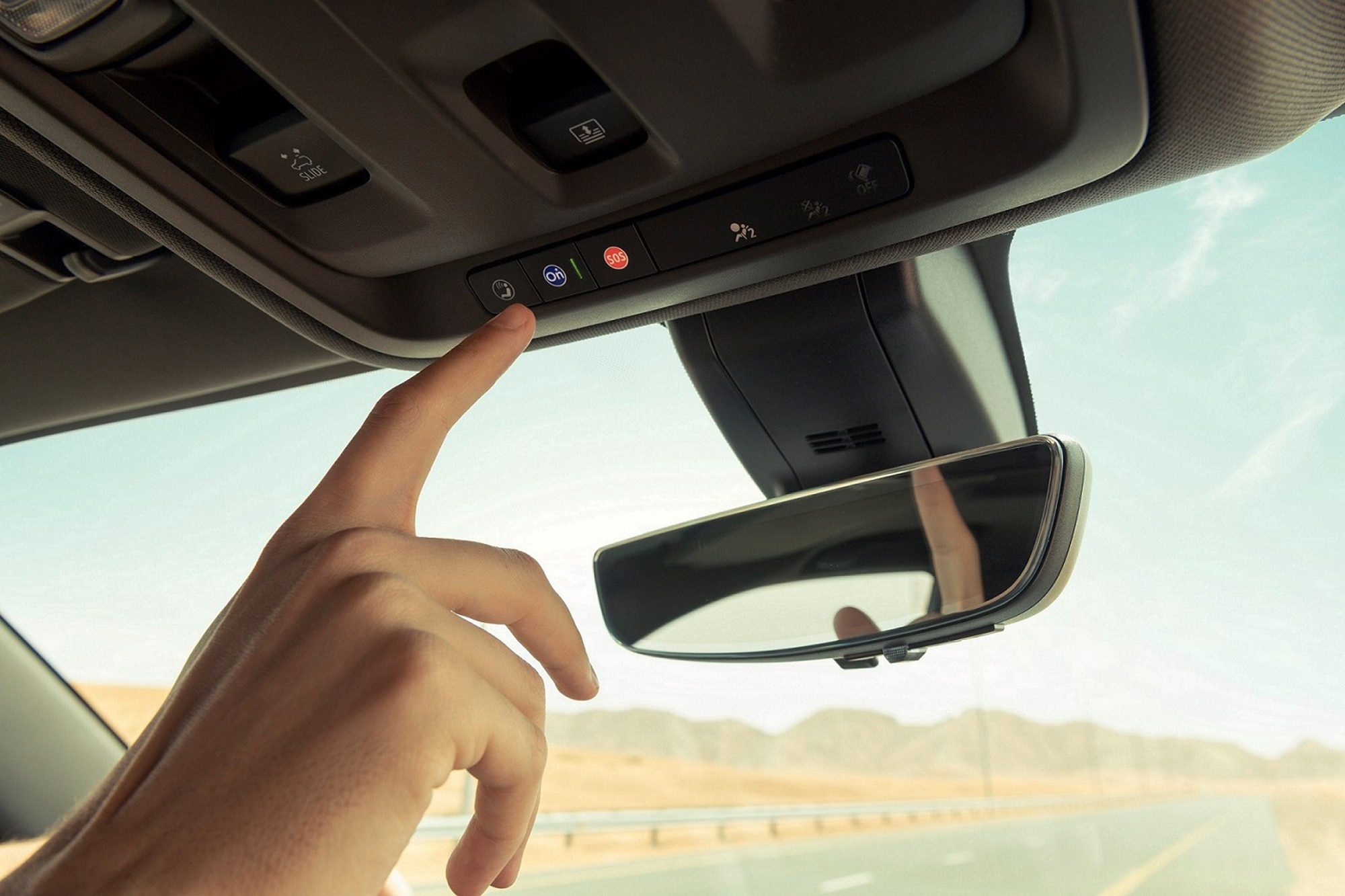
- OnStar Buttons (Usually Blue): Located in the overhead console or rearview mirror. These buttons allow you to initiate a call to OnStar. The red emergency button activates priority emergency services.
- Vehicle Data Bus Interface: The VCIM connects to the vehicle's data bus (CAN bus, LIN bus, etc.) to access vehicle information such as speed, airbag deployment status, and diagnostic trouble codes.
How OnStar Works: The Technical Rundown
Here's a breakdown of the typical communication flow within the OnStar system:
- Event Trigger: An event occurs, such as pressing the blue OnStar button, an airbag deployment, or a request from the owner via the OnStar mobile app.
- VCIM Activation: The VCIM detects the event and initiates a cellular connection to the OnStar call center.
- Data Transmission: The VCIM transmits relevant data to the OnStar call center, including vehicle location, diagnostic information, and the nature of the request (e.g., roadside assistance, emergency services).
- Advisor Interaction: An OnStar advisor receives the data and speaks to the vehicle occupant (if possible) to assess the situation and provide assistance.
- Action Taken: The OnStar advisor takes appropriate action, such as dispatching emergency services, contacting roadside assistance, or providing navigation guidance.
- Two-Way Communication: Throughout the process, the VCIM maintains two-way communication with the OnStar call center, allowing for continuous monitoring and support.
Real-World Use: Basic Troubleshooting Tips
Here are some common OnStar issues and how to approach them:
- No Connection: Check the cellular signal strength indicator in the vehicle's information display (if available). If the signal is weak or non-existent, try moving to a location with better coverage. If the problem persists, check the cellular antenna connection to the VCIM. A loose or corroded connection can cause signal loss.
If you suspect an antenna issue, a VSWR (Voltage Standing Wave Ratio) meter can be used to test the antenna's efficiency. High VSWR indicates a problem with the antenna or cabling.
- Error Messages: Scan the vehicle's computer for diagnostic trouble codes (DTCs) using an OBD-II scanner. Pay attention to codes related to the VCIM or telematics system. Example: Code B1001 indicates a problem with the VCIM's internal memory. Research the code and follow the manufacturer's recommended diagnostic procedure.
- GPS Issues: If the GPS is not functioning correctly, ensure that the GPS antenna has a clear view of the sky. Obstructions such as trees or buildings can interfere with GPS reception. Check the GPS antenna connection to the VCIM.
- Audio Problems: If you cannot hear the OnStar advisor or the advisor cannot hear you, check the microphone and speaker connections. Ensure that the volume is turned up. If the problem persists, the microphone or speaker may be faulty.
Safety: Highlighting Risky Components
Working with automotive electrical systems can be dangerous if proper precautions are not taken. The OnStar system is integrated with other critical vehicle systems, so it's essential to be aware of the following:
- Airbag System: The OnStar system is often connected to the airbag system for automatic crash response. Do not attempt to disconnect or modify any wiring related to the airbag system without proper training and precautions. Accidental deployment of an airbag can cause serious injury. Always disconnect the vehicle's battery before working on the airbag system.
- High-Voltage Systems (Hybrid/Electric Vehicles): If you are working on a hybrid or electric vehicle, be aware of the high-voltage electrical systems. The OnStar system may be connected to these systems. Consult the vehicle's service manual for specific safety precautions.
- Power Supply: Disconnect the negative terminal of the vehicle's battery before working on any electrical components. This will prevent accidental short circuits and electrical shocks. Use a multimeter to verify that there is no voltage present before touching any wires or connectors.
- Proper Grounding: Ensure that all electrical connections are properly grounded to prevent electrical noise and interference. Poor grounding can cause erratic behavior in the OnStar system and other vehicle electronics.
Detailed Onstar Diagram - Downloadable File Available
We have a detailed diagram of a common Onstar setup available for download. It includes a breakdown of the components, wiring schematics, and connector pinouts. This diagram will be invaluable for troubleshooting, understanding the system's architecture, and planning any modifications.
This information is intended for educational purposes only. Always consult the vehicle's service manual and follow proper safety procedures when working on automotive electrical systems. If you are not comfortable working on these systems, seek the assistance of a qualified technician.