How To Start A Car Remotely
So, you're thinking about remote starting your car. That's a great upgrade! It's super convenient on those cold winter mornings or scorching summer afternoons. This article dives into the wiring and components that make remote starting possible. We'll cover how it all connects, what can go wrong, and what to watch out for. Think of this as a detailed roadmap; we have a downloadable wiring diagram available (link at the end) to make things even clearer. Let's get started!
Understanding the Remote Start System: Why Bother?
Why bother understanding this diagram? Well, for a few reasons. Maybe your aftermarket remote start system is acting up, and you want to troubleshoot it yourself. Or perhaps you're considering installing one and want a solid grasp of what's involved beyond the marketing hype. Or maybe you just like tinkering and understanding how things work – that's cool too! Knowing the ins and outs of the remote start system can save you money on repairs, help you choose the right components for an upgrade, and give you a deeper understanding of your vehicle's electrical system. The diagram we offer is particularly useful for identifying individual components and their connections within a specific remote start kit, although the general principles apply across many systems.
Key Specs and Main Parts
A typical remote start system isn't just one box; it's a collection of interconnected components. Here's a breakdown of the key players:
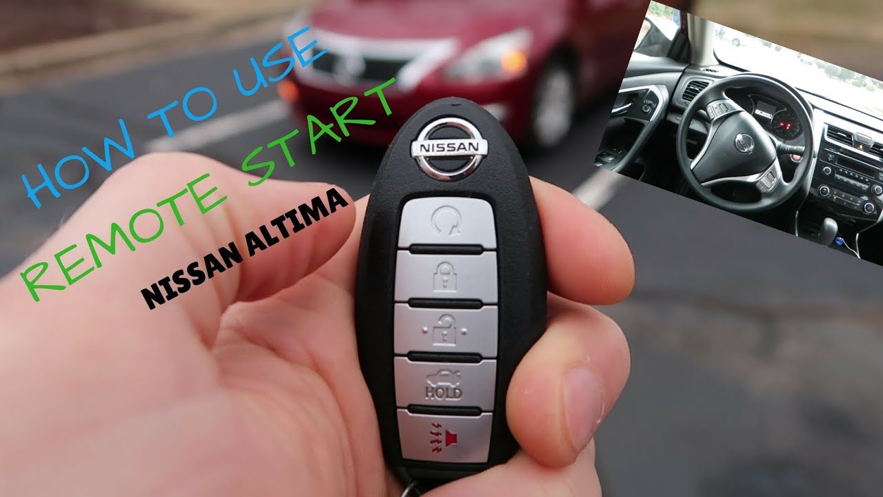
- Remote Control/Transmitter: The device you use to initiate the remote start sequence. It communicates wirelessly with the receiver.
- Receiver/Control Module: The "brains" of the operation. It receives the signal from the remote, interprets it, and sends commands to other parts of the system. This module often houses the bypass module interface.
- Bypass Module: This is crucial. Modern cars have sophisticated anti-theft systems. The bypass module tricks the car into thinking the key is present during a remote start, preventing the immobilizer from shutting down the engine. It often interacts with the vehicle's data bus (CAN bus).
- Hood Pin Switch: A safety feature. If the hood is open, the remote start system is disabled. This prevents accidental starting while you're working under the hood.
- Wiring Harness: A collection of wires that connects all the components. Often includes connectors for easy installation and removal.
- Relays: Electrically operated switches. They allow the low-current signal from the control module to switch higher-current circuits, such as the starter motor.
- Antenna: Receives the signal from the remote control, often mounted on the windshield.
Key Specs to consider: Voltage (typically 12V DC), Current draw (especially during cranking), Operating temperature range, and communication frequency (for the remote).
Deciphering the Diagram: Symbols and Conventions
A wiring diagram is a visual language, so understanding the symbols is essential. Here's a quick guide:
- Lines: Represent wires. The thickness of the line doesn't usually indicate wire gauge, but may differentiate between power/ground and signal wires in some diagrams.
- Colors: Critical! Each wire has a specific color code (e.g., Red for +12V, Black for Ground, etc.). These colors should be clearly marked on the diagram. They help you identify the correct wires in your car's harness.
- Circles/Dots: Indicate connection points (splices or terminals). A filled dot usually means a permanent connection. An empty circle may indicate a removable connector.
- Rectangles: Often represent electronic components like the control module, bypass module, or relays.
- Ground Symbol (usually three descending horizontal lines): Indicates a connection to the chassis ground (the metal body of the car).
- Fuse Symbol (often a zigzag line inside a rectangle): Shows the location of a fuse. Always check the fuse rating (in Amps) on the diagram.
- Relay Symbol: A coil of wire connected to a switch. When the coil is energized, the switch changes position, connecting or disconnecting a circuit.
Color Codes: Standard color codes include: Red for power, Black for ground, Yellow for ignition, Blue for starter, Green for tach signal (engine speed), and White for parking lights. However, these can vary between manufacturers, so always refer to the specific diagram for your system.
How It Works: The Remote Start Sequence
Let's break down the sequence of events when you press the remote start button:
- Signal Transmission: You press the button on the remote. The transmitter sends a coded radio frequency (RF) signal to the receiver in your car.
- Signal Reception and Validation: The receiver/control module receives the signal. It checks the code against its stored codes to ensure it's a valid command.
- Safety Check: The control module checks safety interlocks, such as the hood pin switch. If the hood is open, the system will not start.
- Bypass Activation: The bypass module is activated. This typically involves sending signals to the car's immobilizer system, mimicking the presence of the key. This might involve sending a specific resistance value, a CAN bus message, or a data signal.
- Accessory Power: The control module activates the accessory circuit, turning on things like the radio and climate control (if programmed to do so).
- Ignition Power: The ignition circuit is energized, preparing the engine for starting.
- Starter Engagement: The starter motor is engaged, cranking the engine. The control module monitors the engine speed (using a tach signal or voltage sensing) to determine when the engine has started.
- Run Mode: Once the engine is running, the starter is disengaged, and the system maintains the engine running for a pre-set time (typically 10-20 minutes).
Real-World Use: Basic Troubleshooting Tips
Things don't always go smoothly. Here are some common problems and how to address them:
- Remote Start Doesn't Work At All:
- Check the remote's batteries.
- Check the fuses in the remote start system and the car's electrical system.
- Verify the hood pin switch is properly installed and functioning.
- Check the antenna connection and position.
- Ensure the bypass module is correctly programmed and connected. This is a very common cause of failure!
- Engine Cranks But Doesn't Start:
- The bypass module may not be working correctly. Double-check its connections and programming.
- The fuel pump may not be activating. Check the fuel pump relay and fuse.
- There may be an issue with the tach signal or voltage sensing. Verify the connection and signal strength.
- Engine Starts and Immediately Dies:
- Almost certainly a bypass module issue. The immobilizer is shutting down the engine.
- Could also be an issue with the fuel system losing pressure.
- Parking Lights Don't Flash:
- Check the parking light wire connection.
- Check the parking light fuse in the remote start system.
Important: When troubleshooting, always use a multimeter to check for voltage and continuity. A test light can also be useful, but a multimeter provides more accurate readings.
Safety First: Highlighting Risky Components
Working with automotive electrical systems can be dangerous. Here are some key safety considerations:
- Disconnect the Battery: Always disconnect the negative battery terminal before working on any electrical wiring. This prevents short circuits and potential electrical shocks.
- Airbags: Be extremely careful when working near airbags. Incorrect wiring can cause them to deploy unexpectedly. Consult your vehicle's service manual for airbag deactivation procedures.
- Fuel System: Avoid sparks or open flames when working near the fuel system. Fuel vapors are highly flammable.
- High-Current Circuits: The starter circuit and battery cables carry high currents. Avoid touching these circuits when the battery is connected.
- Proper Grounding: Ensure all ground connections are clean and secure. A poor ground can cause all sorts of electrical problems.
- Wire Gauges: Use the correct wire gauge for each connection. Undersized wires can overheat and cause fires. Refer to the diagram for proper wire sizes.
- Heat Shrink Tubing: Use heat shrink tubing to insulate all wire splices. This provides a waterproof and durable connection.
Warning: Incorrectly installed remote start systems can damage your car's electrical system, void your warranty, or even create a fire hazard. If you're not comfortable working with automotive electrical systems, it's best to have a professional install the remote start system.
By understanding the wiring diagram and the principles of operation, you can diagnose and repair issues with your remote start system. This knowledge also allows you to upgrade and customize the system to your specific needs. We hope this detailed explanation has been helpful. Remember to always prioritize safety when working on your car's electrical system.
We have the complete wiring diagram available for download. Click here to download the remote start wiring diagram.