How To Start Car Using Remote
Remote car starters have become increasingly popular, offering convenience and comfort, especially in extreme weather conditions. But understanding how these systems work, from the wiring to the control modules, empowers you to troubleshoot issues, perform upgrades, and even build custom solutions. This article provides a technical deep dive into the anatomy of a remote car starter system, equipping you with the knowledge to diagnose problems and work with these increasingly common automotive components.
Purpose of Understanding the Remote Start Diagram
Having access to and understanding a remote start system wiring diagram is invaluable for several reasons:
- Repairs and Troubleshooting: When your remote start fails, the diagram helps you pinpoint the source of the problem. You can trace wires, test connections, and identify faulty components.
- Upgrades and Modifications: Planning to add new features, like smartphone integration or a longer-range antenna? The diagram provides the blueprint for integrating new components into the existing system.
- DIY Installations: For experienced DIYers, the diagram is essential for installing a remote start system from scratch. It guides you through the complex wiring process and ensures proper connections.
- Education and Learning: Understanding the system’s architecture provides a deeper understanding of automotive electronics in general. It’s a valuable stepping stone for tackling more complex automotive projects.
Key Specs and Main Parts
A remote start system consists of several key components, each with its specific function. Key specs of the remote start system are input voltage (usually 12V DC, matching the vehicle's electrical system), current draw during standby and operation, operating frequency of the remote transmitter, and the range of the remote. Here's a breakdown of the primary parts:
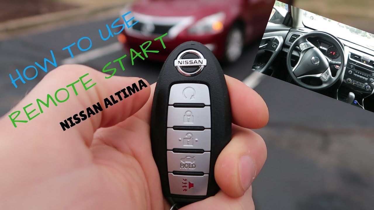
- Remote Transmitter (Key Fob): This is the device you use to initiate the remote start sequence. It transmits a radio frequency (RF) signal to the receiver in the vehicle.
- Receiver/Control Module: This module receives the RF signal from the transmitter, verifies its authenticity, and then activates the starting sequence. It's the brains of the operation.
- Wiring Harness: This network of wires connects all the components of the remote start system. Wires are typically color-coded for easy identification.
- Hood Pin Switch: A safety device that prevents the engine from starting remotely if the hood is open. This prevents accidental starting while someone is working under the hood.
- Brake Pedal Switch: Another crucial safety component. Pressing the brake pedal usually disengages the remote start system, preventing unexpected vehicle movement.
- Tachometer Wire (or Virtual Tach): This wire (or a virtual tach signal derived from the car's CAN bus) allows the control module to monitor engine RPM. This is crucial for preventing over-cranking.
- Ignition Wires: These are the wires that connect to the vehicle's ignition system, allowing the remote start to simulate turning the key in the ignition. Typical wires include the ignition wire, starter wire, accessory wire, and sometimes a second accessory wire.
- Door Lock/Unlock Interface: Often, remote start systems also incorporate door lock and unlock functionality. This interface connects to the vehicle's door locking system.
- Bypass Module (if needed): Modern vehicles often have sophisticated anti-theft systems that prevent unauthorized starting. A bypass module is required to temporarily disable these systems during remote start. The type of bypass module needed depends on the specific vehicle.
Understanding Wiring Diagram Symbols
Wiring diagrams use standardized symbols to represent different components and connections. Learning to interpret these symbols is essential for reading and understanding the diagram.
- Lines: Lines represent wires. The thickness of the line doesn't usually indicate wire gauge, but rather visual clarity. Dashed lines may indicate wires that are optional or only present in certain configurations. Different colors on the wires indicate different functions.
- Circles: Circles often represent connection points or splices in the wiring. A circle with a diagonal line through it can represent a ground connection.
- Rectangles: Rectangles often represent components like relays, switches, or control modules.
- Resistors: A jagged line represents a resistor. The value of the resistance is typically indicated next to the symbol.
- Capacitors: Two parallel lines represent a capacitor. The capacitance value is usually indicated next to the symbol.
- Diodes: A triangle pointing to a line represents a diode. The direction of the triangle indicates the direction of current flow.
- Relays: A relay is represented by a coil (often drawn as a looped wire) and a switch. The coil, when energized, closes the switch, completing a circuit. Understanding how relays function is critical for troubleshooting remote start systems.
- Colors: Wire colors are typically abbreviated (e.g., RED, BLU, GRN, YEL, BLK). Following the correct wire colors is crucial for proper installation.
How It Works: The Remote Start Sequence
The remote start sequence follows a specific set of steps:
- Transmitter Activation: You press the start button on the remote transmitter. This sends a unique RF signal.
- Receiver Verification: The receiver/control module receives the RF signal and verifies its authenticity. This may involve checking a security code to prevent unauthorized access.
- Safety Check: The control module checks the safety switches (hood pin, brake pedal). If the hood is open or the brake pedal is pressed, the start sequence is aborted.
- Bypass Activation (if required): The bypass module is activated, temporarily disabling the vehicle's anti-theft system. This allows the remote start system to start the engine without triggering the alarm.
- Ignition Activation: The control module energizes the appropriate ignition wires, simulating the key being turned in the ignition. This includes the ignition wire, accessory wire, and starter wire.
- Engine Cranking: The starter motor is engaged, cranking the engine until it starts. The control module monitors the tachometer signal (or uses a virtual tach) to determine when the engine has started.
- Engine Running: Once the engine is running, the starter motor is disengaged. The control module continues to monitor the engine RPM to ensure it doesn't stall.
- Shutdown: The engine will run for a predetermined amount of time (usually 10-15 minutes) or until you press the stop button on the remote. Pressing the brake pedal will also typically shut down the engine.
Real-World Use: Basic Troubleshooting Tips
Here are some common problems and troubleshooting tips:
- Remote start not working at all:
- Check the battery in the remote transmitter.
- Check the fuse for the remote start system.
- Verify that the hood pin switch is properly installed and functioning.
- Engine cranks but doesn't start:
- Check the tachometer wire connection. The control module may not be receiving the correct RPM signal.
- The bypass module may not be functioning correctly. This is common on newer vehicles with sophisticated anti-theft systems.
- Ensure that all the necessary ignition wires are properly connected.
- Engine starts and then immediately shuts off:
- This can also be related to the tachometer signal. The control module may be misinterpreting the engine RPM.
- Check for vacuum leaks that could be causing the engine to stall.
- System activating randomly:
- RF Interference may be triggering the system. Try relocating the receiver module.
- A short circuit in the wiring could be falsely triggering the system.
Use a multimeter to test for voltage and continuity in the wiring. A multimeter is invaluable for diagnosing electrical problems.
Safety Considerations
Working with automotive electrical systems can be dangerous. Here are some important safety precautions:
- Disconnect the Battery: Always disconnect the negative terminal of the battery before working on any electrical components. This prevents accidental short circuits and potential damage to the vehicle's electrical system.
- Identify High-Current Wires: Be extremely careful when working with high-current wires, such as the starter wire and the battery wire. These wires can carry significant amounts of current and can cause serious burns or electrical shock.
- Use Proper Tools: Use insulated tools to prevent electrical shock.
- Double-Check Connections: Before reconnecting the battery, carefully double-check all connections to ensure they are secure and properly insulated.
- Airbags: Be aware of the location of airbags. Disconnecting the battery may or may not prevent deployment but exercise caution.
Warning: The starter wire and ignition wires carry high current. Incorrect wiring can damage the vehicle's electrical system or cause a fire.
Working with CAN bus systems requires specialized knowledge and tools. Improper connections can damage the vehicle's computer system.
Always consult the vehicle's service manual and the remote start system's installation manual before attempting any work.
We have the remote start system wiring diagram file available for download to provide a visual aid for your project. This diagram shows typical remote start wiring schematics and provides a comprehensive overview of the connections involved.