How To Start Car Without Key
Okay, let's talk about bypassing the key ignition system on a modern car. Now, I want to be very clear upfront: this information is strictly for educational purposes and emergency situations. We're talking about scenarios where you're stranded and the key is genuinely lost or broken. Bypassing the ignition system can potentially damage your vehicle's electronics and, depending on your local laws, could have serious legal consequences if done improperly or without legitimate reason. Understanding the electrical architecture is crucial for diagnostics, repairs, and modifications. We are not responsible for any damage or loss caused. This is just information, not advice.
Why This Matters: Reading the Starting Circuit Diagram
Understanding the starting circuit diagram is invaluable for several reasons. Imagine you're dealing with a no-start condition, and you've already checked the battery and starter. A diagram helps you trace the electrical path from the ignition switch all the way to the starter solenoid, allowing you to pinpoint the exact component causing the problem. Are you retrofitting an aftermarket security system? Knowing which wires control the immobilizer can save you hours of headaches and potentially prevent frying expensive electronics. Modification and repair are not recommended, unless with the appropriate training and experience.
Having this knowledge also allows you to understand how anti-theft systems like immobilizers work and, in extreme emergency situations, how to potentially bypass them. However, again, stress is on extreme emergency. Misuse of this information is highly discouraged.
Key Specs and Main Parts of the Starting Circuit
The starting circuit, while complex in modern vehicles, revolves around a few core components:
- Battery: Provides the initial electrical power to the system. Crucial voltage and amperage ratings.
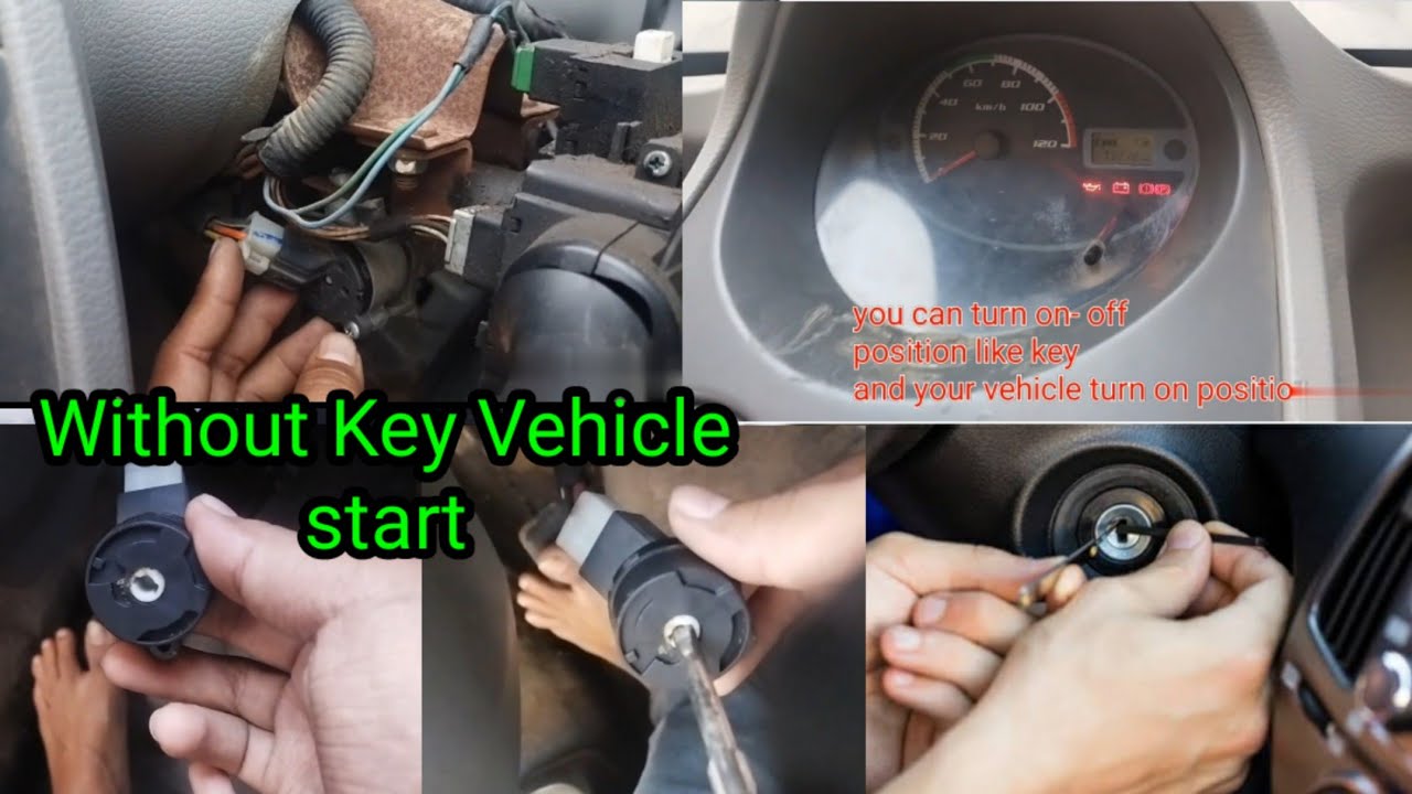
- Ignition Switch: The switch activated by your key (or start button in newer cars). Has multiple positions: OFF, ACC (Accessory), ON, and START.
- Starter Relay: A high-current switch that allows a low-current signal from the ignition switch to activate the starter solenoid.
- Starter Solenoid: Engages the starter motor with the flywheel and provides high current to the starter motor.
- Starter Motor: Cranks the engine, initiating the combustion process.
- Immobilizer System (if equipped): A security system that prevents the engine from starting unless a valid key transponder is detected. This is often integrated with the ECU (Engine Control Unit).
- ECU (Engine Control Unit): Modern cars rely heavily on the ECU. It controls fuel injection, ignition timing, and interacts with the immobilizer.
Key specifications include wire gauge (determines current-carrying capacity), relay amperage ratings, and voltage levels at various points in the circuit (typically 12V DC). Understanding these specs is important for selecting replacement parts and troubleshooting voltage drops.
Deciphering the Diagram: Symbols, Lines, and Colors
Electrical schematics use standardized symbols to represent components. Here's a quick rundown:
 : Battery (long line is positive, short line is negative)
 : Resistor
 : Capacitor
 : Ground
- Circle with a diagonal line: Lamp/Bulb
- Rectangle with labeled terminals: Relay
Lines represent wires. Solid lines typically indicate a direct connection, while dashed lines may indicate a shielded wire or a connection through a connector. Line thickness can sometimes indicate wire gauge. Colors are crucial. Common color codes include:
- Red (RD): Battery power
- Black (BK): Ground
- Yellow (YE): Often used for control signals
- Blue (BL): Another common control signal color
- Green (GN): Often associated with sensors
Pay close attention to the labels next to the wires. These indicate the wire's circuit or function. For example, "30" and "87" are commonly used to designate terminals on a relay.
Understanding the abbreviations is essential. Refer to your car's repair manual or online resources for a complete list.
How It Works: Tracing the Starting Sequence
Let's walk through a simplified version of the starting sequence:
- You insert the key and turn it to the START position.
- The ignition switch sends a low-current signal to the starter relay coil.
- If the immobilizer system is satisfied (key transponder is valid), the ECU allows the ground path for the starter relay coil to complete, energizing the relay.
- The energized starter relay closes, connecting the battery's positive terminal to the starter solenoid.
- The starter solenoid engages, pushing the starter motor pinion gear into contact with the flywheel and simultaneously providing high current to the starter motor.
- The starter motor cranks the engine.
- Once the engine starts, you release the key, and the ignition switch returns to the ON position. The starter relay disengages, and the starter motor stops cranking.
In modern cars, the ECU plays a much larger role. It monitors various sensors (crankshaft position, camshaft position, etc.) to ensure the engine is ready to start. It also communicates with the immobilizer system to verify the key's validity. If any of these conditions are not met, the ECU will prevent the starter from engaging, even if the ignition switch is in the START position.
Real-World Use: Basic Troubleshooting Tips
Here are some basic troubleshooting tips using the starting circuit diagram:
- No crank, no start: Use a multimeter to check for voltage at the starter relay coil when the ignition switch is in the START position. If there's no voltage, the problem lies upstream (ignition switch, wiring, or immobilizer system).
- Clicking sound, no crank: The starter solenoid might be engaging, but the starter motor isn't receiving enough current. Check the connections to the starter motor and solenoid for corrosion. Also, test the battery voltage under load.
- Engine cranks but doesn't start: The starter circuit is working, but the engine isn't receiving fuel or spark. This could be a problem with the fuel pump, ignition coils, or sensors.
Always use a multimeter or test light to verify voltage and continuity before replacing any parts. Use the schematic to systematically trace the circuit and identify the point where the voltage is lost or the circuit is broken.
Safety: Handling Risky Components
Working with electrical systems can be dangerous. Here are some safety precautions:
- Disconnect the battery: Always disconnect the negative terminal of the battery before working on the electrical system. This prevents accidental shorts and potential electrical shocks.
- Work in a well-lit area: Good lighting is essential for seeing what you're doing and avoiding mistakes.
- Use insulated tools: Use tools with insulated handles to protect yourself from electrical shocks.
- Be careful around the starter motor: The starter motor can draw a large amount of current, which can generate heat. Avoid touching the starter motor immediately after cranking the engine.
- Never bypass safety features: Do not disable or bypass safety features like immobilizers unless absolutely necessary in an emergency situation.
- Be aware of the SRS (Supplemental Restraint System) or airbags: Disconnecting or tampering with SRS components can cause them to deploy unexpectedly, resulting in serious injury. Consult your car's repair manual for proper procedures before working near these components.
- Fuel lines near by: Starter and Fuel delivery systems may be in close proximity. Avoid accidental damage to fuel lines to prevent explosion/fire.
The high-current wires leading to the starter motor and solenoid are particularly dangerous. A short circuit in these wires can cause a fire or serious burns. Always handle these wires with care.
This article provides a basic overview of how to understand and potentially bypass the starting circuit. Remember, this is a complex system, and working on it requires a solid understanding of electrical principles and automotive technology. Take proper safety precautions, and always consult your car's repair manual for specific information about your vehicle.
We have a general schematic file available for download. It provides a visual overview of a typical starting system. Please contact us to request access to the file. Remember that this is a generic diagram and may not perfectly match your specific vehicle. Please use this information wisely and responsibly.