How To Start Your Car Remotely
So, you're looking to delve into the world of remote starting your car. Whether you're facing frigid winters, scorching summers, or just want the convenience of a warm engine ready to go, understanding the inner workings of a remote start system is crucial. This article will break down the common components and their functions, like a trusted mechanic would, so you can confidently tackle repairs, modifications, or simply expand your automotive knowledge.
Purpose of Understanding the Remote Start System
Why bother understanding the ins and outs of your remote start? Well, knowledge is power, especially when it comes to your vehicle. A clear understanding of the system allows for:
- Effective Troubleshooting: When your remote start fails, you won't be stranded, guessing at the problem. You'll be equipped to diagnose common issues.
- Safe Repairs: Working with electrical systems demands respect. Knowing the components and their functions reduces the risk of damaging your car or yourself.
- Informed Modifications: Want to upgrade your system or integrate it with other features? Understanding the core principles will prevent costly mistakes.
- General Automotive Knowledge: Even if you don't plan on doing extensive work yourself, understanding this system contributes to a broader understanding of vehicle electronics.
Key Specs and Main Parts of a Remote Start System
Remote start systems, while seemingly complex, are built upon a relatively small set of essential components. Let's break them down:
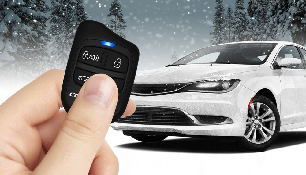
- Remote Transmitter (Key Fob): This is the device you carry around. It sends the start/stop signals to the receiver. Specifications include operating frequency (e.g., 433MHz, 900MHz), range (in feet), and battery type.
- Remote Receiver/Control Module: This module is the brains of the operation. It receives the signal from the transmitter, verifies its validity, and then initiates the starting sequence. Key specs include voltage range (typically 12V DC), current draw (when idle and active), and compatibility with vehicle security systems.
- Starter Interrupt Relay: This relay interrupts the starter circuit to prevent accidental starting when the vehicle is already running or when a security system is triggered. It has specific voltage and current ratings that must match your vehicle's starter system.
- Tachometer Input (Tach Wire): This wire connects to the vehicle's tachometer signal wire, allowing the remote start module to monitor engine RPM. This information is crucial for determining if the engine has started successfully and to prevent over-cranking.
- Brake Shutoff Input: A safety feature! This input connects to the brake pedal switch. Pressing the brake pedal while the engine is running under remote start will shut it down.
- Hood Pin Switch: Another crucial safety feature. This switch is mounted under the hood and prevents the engine from starting remotely if the hood is open.
- Ignition Wires: These wires connect directly to the vehicle's ignition harness, providing power to the necessary circuits during remote start. Typically, you'll find wires for ignition 1, ignition 2, accessory, and starter.
- Data Interface Module (Optional): Newer vehicles often use a data bus (like CAN bus) for communication. A data interface module simplifies installation by allowing the remote start module to communicate with the vehicle's computer system without needing to tap into individual wires for every function.
Understanding Wiring Diagram Symbols
A remote start wiring diagram looks intimidating at first, but it’s just a roadmap using specific symbols and conventions. Here’s a breakdown:
- Lines: Solid lines represent wires. Dashed lines often indicate wires related to optional features or connections that may not be present in all vehicles. The thickness of the line doesn't usually represent wire gauge (size), but consult the system documentation.
- Colors: Wire colors are standardized (though can differ slightly between manufacturers). Red is typically power (12V+), black is ground, and other colors are assigned to specific functions (e.g., blue for starter, yellow for ignition, green for tachometer). The diagram key will specify color assignments.
- Icons: Various icons represent components. A circle with a resistor symbol represents a resistor. A rectangle with a diagonal line is a relay. A switch is depicted as a line connecting to two or more points. Detailed symbols, like the vehicle’s ECU, will have specific representations.
- Ground Symbol: Typically represented as three horizontal lines, decreasing in length from top to bottom, or a similar symbol resembling a triangle. This signifies a connection to the vehicle's chassis ground.
How a Remote Start System Works
Here's a simplified step-by-step breakdown of how a remote start system functions:
- Signal Transmission: You press the start button on the remote transmitter (key fob). This sends a radio frequency (RF) signal to the receiver module in your car.
- Signal Reception and Verification: The receiver module receives the RF signal. It checks if the signal is valid (i.e., matches the programmed code for your specific remote).
- Safety Check: The receiver module verifies that the safety conditions are met. Is the hood closed (hood pin switch)? Is the parking brake engaged? Is the vehicle in Park (automatic transmission) or Neutral (manual transmission, if supported and properly configured)?
- Starter Interrupt Relay Bypass: If all safety checks pass, the starter interrupt relay is temporarily bypassed, allowing the starter to engage.
- Ignition Activation: The receiver module activates the necessary ignition wires (ignition 1, ignition 2, accessory) to power up the vehicle's electrical system.
- Starter Engagement: The module engages the starter motor until the engine starts. It monitors the tachometer signal to determine if the engine has started successfully. If the engine doesn't start after a pre-determined time, the starter is disengaged to prevent damage.
- Engine Monitoring: Once the engine is running, the module continues to monitor the tachometer signal to ensure the engine remains running.
- Shut-Off Mechanism: The engine will shut off automatically after a pre-set run time (e.g., 15 minutes) or if the brake pedal is pressed, the hood is opened, or the stop button is pressed on the remote.
Real-World Use – Basic Troubleshooting Tips
Remote start acting up? Here are a few basic troubleshooting tips:
- Check the Batteries: Start with the obvious – replace the batteries in your remote transmitter.
- Range Issues: If the range is poor, try moving closer to the car. Obstructions (buildings, other vehicles) can interfere with the RF signal. Ensure the receiver antenna is properly positioned (usually on the windshield).
- Engine Fails to Start: Double-check all safety switches (hood pin, brake pedal). Make sure the hood is completely closed. Ensure the vehicle is in Park or Neutral. If your car requires the security system to be disarmed, make sure that step is being performed correctly.
- System is Completely Dead: Check the fuses related to the remote start system (typically located in the vehicle's fuse box). A blown fuse is a common cause of failure.
- Check the Tachometer Wire: If the remote start system cranks but the engine doesn't start, the tachometer wire might not be properly connected. The system needs this signal to know when the engine has started.
Safety – Highlight Risky Components
Working with automotive electrical systems requires caution. Here are some areas where you need to be extra careful:
- Airbag System: Never disconnect or tamper with any wiring related to the airbag system unless you are a certified technician. Accidental airbag deployment can cause serious injury.
- Fuel System: Exercise extreme caution when working near the fuel system. Disconnect the negative battery terminal before working on any electrical components near the fuel tank or fuel lines to prevent sparks.
- Electrical Shorts: Always disconnect the negative battery terminal before working on any electrical wiring. Use a multimeter to verify that wires are properly connected and that there are no short circuits. An electrical short can damage your car's electrical system and even cause a fire.
- Relays and Solenoids: These components can become hot during operation. Allow them to cool down before touching them.
- Data Interface Modules: Ensure that any data interface modules you use are compatible with your vehicle and that you follow the manufacturer's instructions carefully. Incorrect configuration can cause serious problems with your car's computer system.
- Wiring Errors: Take your time and double-check all wiring connections. Incorrect wiring can damage the remote start system, the vehicle's electrical system, or both. Always consult the wiring diagram and use a multimeter to verify connections.
By understanding the components, wiring, and operation of your remote start system, you can confidently troubleshoot issues, perform minor repairs, and even upgrade your system. Remember to always prioritize safety and consult the vehicle's service manual and the remote start system's documentation for specific instructions and warnings.
We have a detailed wiring diagram file available for download. This diagram will help you visualize the connections and understand the system's layout. It's a valuable resource for anyone looking to work on their remote start system.