How To Test A 2 Wire Coolant Temp Sensor
Diagnosing engine problems can be a frustrating task, but pinpointing the culprit often comes down to understanding how individual components work and knowing how to test them. One crucial sensor in modern engines is the Coolant Temperature Sensor (CTS), and a faulty one can lead to a myriad of issues, from poor fuel economy to difficulty starting. This article will guide you through the process of testing a 2-wire CTS, providing you with the knowledge and techniques needed to diagnose potential problems with confidence.
Background: The Engine Cooling System and the CTS
To understand the role of the CTS, we first need to briefly discuss the engine cooling system. The engine cooling system is responsible for maintaining the engine at its optimal operating temperature. This is achieved by circulating coolant (typically a mixture of water and antifreeze) through the engine block and cylinder head. The coolant absorbs heat generated by combustion and then flows to the radiator, where the heat is dissipated into the atmosphere.
The CTS plays a vital role in this system by providing the engine control unit (ECU) with real-time information about the coolant temperature. The ECU, also sometimes referred to as a PCM (Powertrain Control Module), uses this data to adjust various engine parameters, including:
- Fuel Injection: A cold engine requires a richer air-fuel mixture to start and run smoothly. The ECU uses the CTS data to increase fuel injection during cold starts and gradually decrease it as the engine warms up.
- Ignition Timing: Coolant temperature influences ignition timing. The ECU may advance or retard the timing depending on the engine's temperature.
- Idle Speed Control: During cold starts, the ECU increases the idle speed to prevent stalling. This is also based on CTS readings.
- Cooling Fan Operation: The ECU uses CTS data to control the electric cooling fan(s). The fan is typically activated when the coolant temperature reaches a certain threshold.
A malfunctioning CTS can send incorrect temperature readings to the ECU, leading to all sorts of drivability problems. Therefore, accurately testing the CTS is essential for proper engine diagnosis.
Technical Breakdown: How a 2-Wire CTS Works
A 2-wire CTS is typically a thermistor. A thermistor is a type of resistor whose resistance varies significantly with temperature. Specifically, most automotive CTS units are Negative Temperature Coefficient (NTC) thermistors. This means that as the temperature increases, the resistance of the sensor decreases.
Here's how it works in the context of the engine management system:
- Voltage Supply: The ECU provides a stable 5-volt reference voltage (Vref) to the CTS. This voltage is typically routed through a pull-up resistor within the ECU itself. One of the two wires on the CTS connects to this 5V reference.
- Ground Connection: The other wire of the CTS is connected to ground (0V).
- Voltage Drop: The CTS acts as a variable resistor between the 5V reference and ground. As the coolant temperature changes, the resistance of the CTS changes, causing a change in the voltage drop across it.
- ECU Interpretation: The ECU monitors the voltage drop across the CTS. By knowing the fixed resistance of its internal pull-up resistor and the measured voltage, the ECU can calculate the resistance of the CTS and, consequently, the coolant temperature.
Think of it like a simple voltage divider circuit. The ECU knows the initial voltage (5V) and the resistance of its internal resistor. By measuring the voltage at the CTS connection, it can calculate the CTS resistance and infer the temperature.
Testing the CTS: A Step-by-Step Guide
Testing a 2-wire CTS typically involves checking its resistance at different temperatures and verifying the voltage signal it sends to the ECU. Here's a detailed procedure:
- Gather Your Tools: You'll need a multimeter (capable of measuring resistance and voltage), a container to heat water, a thermometer, and access to your vehicle's CTS. Optionally, you might want a wiring diagram for your specific vehicle.
- Locate the CTS: The CTS is usually located in the engine block or cylinder head, near the thermostat housing. Consult your vehicle's repair manual to find its exact location.
- Disconnect the CTS Connector: Carefully disconnect the electrical connector from the CTS. Take care not to damage the connector or the wiring.
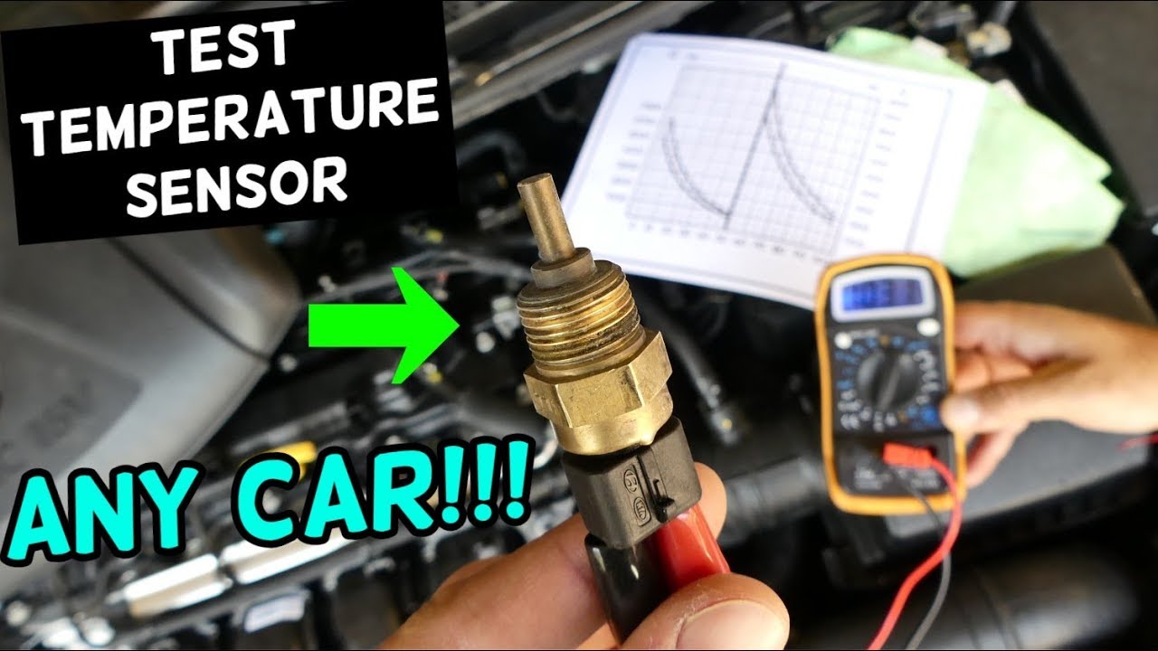
- Resistance Check (Cold): Set your multimeter to measure resistance (Ohms - Ω). Connect the multimeter leads to the two terminals of the CTS. Record the resistance reading. Compare this reading to the expected resistance value at the ambient temperature. You can find this information in your vehicle's repair manual or online specifications. Generally, at room temperature (around 68°F or 20°C), a CTS should have a resistance of around 2,000 to 3,000 Ohms.
- Resistance Check (Hot): Heat some water to a specific temperature (e.g., 180°F or 82°C). Use a thermometer to accurately monitor the water temperature. Carefully submerge the sensor portion of the CTS into the hot water. *Do not submerge the electrical connector.* After a few minutes, measure the resistance again. As the temperature increases, the resistance should decrease significantly. A typical reading at 180°F (82°C) might be around 200 to 300 Ohms.
- Compare Readings to Specifications: Compare your measured resistance values at both cold and hot temperatures to the manufacturer's specifications. If the resistance values are significantly different from the expected values, the CTS is likely faulty and needs to be replaced.
- Voltage Check (Key On, Engine Off): Reconnect the electrical connector to the CTS. Turn the ignition key to the "ON" position but do not start the engine. Set your multimeter to measure DC voltage. Probe the two terminals of the connector (from the wiring harness side, not the sensor side) with your multimeter leads. One wire should show approximately 5V (the reference voltage from the ECU). The other wire should show a voltage that varies depending on the coolant temperature. A cold engine will typically have a lower voltage reading (closer to the 5V reference), while a warm engine will have a higher voltage reading (closer to 0V). The exact voltage will depend on the specific vehicle and sensor characteristics.
- Wiring Check: If you suspect a wiring issue, you can perform a continuity test on both wires between the CTS connector and the ECU connector. This requires identifying the correct pins on the ECU connector, which can be found in the vehicle's wiring diagram. A lack of continuity indicates a broken or damaged wire. You can also check for shorts to ground by measuring the resistance between each wire and the vehicle's chassis ground. A low resistance reading (close to 0 Ohms) indicates a short to ground.
Common Issues and Maintenance Concerns
Several factors can cause a CTS to fail:
- Corrosion: Corrosion can build up on the sensor terminals or inside the sensor housing, leading to inaccurate readings.
- Physical Damage: The CTS can be damaged by impacts or excessive vibration.
- Internal Failure: The thermistor inside the sensor can simply fail over time due to wear and tear.
- Wiring Issues: Damaged or corroded wiring can also cause problems with the CTS signal.
- Coolant Contamination: Contaminated coolant can affect the sensor's accuracy.
Regular maintenance can help prevent CTS failures. This includes:
- Regular Coolant Flushes: Flushing the cooling system according to the manufacturer's recommendations helps remove contaminants that can damage the CTS.
- Visual Inspection: Periodically inspect the CTS and its wiring for any signs of damage or corrosion.
- Proper Coolant Mix: Always use the correct coolant mixture (typically 50/50 water and antifreeze) to ensure proper cooling system performance.
Do's and Don'ts / Best Practices
Here are some important do's and don'ts to keep in mind when testing a CTS:
- Do consult your vehicle's repair manual for specific testing procedures and specifications.
- Do use a high-quality multimeter for accurate measurements.
- Do be careful when working with hot water to avoid burns.
- Do disconnect the battery's negative terminal before working on the electrical system to prevent short circuits.
- Don't submerge the electrical connector of the CTS in water.
- Don't use excessive force when disconnecting or reconnecting the CTS connector.
- Don't rely solely on the CTS reading to diagnose engine problems. Consider other factors, such as spark plugs, fuel injectors, and vacuum leaks.
Conclusion
Testing a 2-wire CTS is a relatively straightforward process that can save you time and money by helping you accurately diagnose engine problems. By following the steps outlined in this article and using the proper tools, you can confidently assess the condition of your CTS and determine if it needs to be replaced. If you are uncomfortable performing these tests or are unsure about any aspect of the process, it's always best to consult with a qualified mechanic. Replacing a faulty CTS is often a simple and inexpensive repair that can significantly improve your vehicle's performance and fuel economy. Always double-check the manufacturer's specifications for your specific vehicle model and engine when diagnosing any sensor issues.