How To Test A Maf Sensor With A Multimeter
The Mass Air Flow (MAF) sensor is a critical component in modern engine management systems. If it malfunctions, your car can experience a range of performance problems, from poor fuel economy to stalling and even a complete no-start condition. Knowing how to test a MAF sensor with a multimeter is a valuable skill for any experienced DIY mechanic, allowing you to diagnose issues quickly and potentially save a significant amount of money on unnecessary repairs.
Background: The MAF Sensor and Engine Management
To understand why testing the MAF sensor is so important, it's helpful to understand its role in the engine management system. Modern engines rely on a sophisticated network of sensors and actuators controlled by the Engine Control Unit (ECU), sometimes also referred to as the Powertrain Control Module (PCM). The ECU's primary function is to maintain the optimal air-fuel ratio (AFR) for efficient combustion and minimal emissions. This ideal ratio is typically around 14.7:1 (air to fuel, by mass), often referred to as stoichiometric.
The MAF sensor is a crucial input device for the ECU. It measures the mass of air entering the engine. This information, along with data from other sensors like the throttle position sensor (TPS), oxygen sensors (O2 sensors), and engine coolant temperature sensor (ECT), allows the ECU to calculate precisely how much fuel needs to be injected into the cylinders to achieve the desired AFR. Without accurate MAF sensor data, the ECU is effectively flying blind, leading to a rich (too much fuel) or lean (too little fuel) condition.
Technical Breakdown: How the MAF Sensor Works
There are several types of MAF sensors, but the most common type used today is the hot-wire MAF sensor. Here's how it works:
- Heated Wire/Film: The sensor contains a small, electrically heated wire or film element that is exposed to the incoming airflow.
- Temperature Regulation: The ECU controls the current flowing through the wire/film to maintain it at a constant temperature (typically around 200 degrees Celsius) above the ambient air temperature.
- Airflow and Cooling: As air flows across the heated element, it cools the element down. The faster the airflow, the greater the cooling effect.
- Current Adjustment: To maintain the constant temperature, the ECU must increase the current flowing through the wire/film to compensate for the cooling effect of the airflow.
- Voltage Signal: The ECU measures the voltage required to maintain the constant temperature. This voltage is directly proportional to the mass of air flowing into the engine.
- Signal Transmission: The MAF sensor then sends this voltage signal to the ECU, providing it with real-time information about the airflow rate.
Another type of MAF sensor, though less common, is the vane meter or vane airflow sensor. These use a spring-loaded vane that moves in proportion to the airflow. The vane's position is then translated into an electrical signal by a potentiometer. However, these are largely obsolete in modern vehicles.
The voltage signal from the MAF sensor is typically a DC voltage that varies with airflow. At idle, the voltage is typically low (around 1 volt), and it increases as the engine speed and airflow increase. The specific voltage range will vary depending on the make, model, and year of the vehicle.
Testing the MAF Sensor with a Multimeter
Testing a MAF sensor with a multimeter involves checking the sensor's power, ground, and signal wires. Here's a step-by-step guide:
- Safety First: Disconnect the negative battery terminal before working on any electrical components. This prevents accidental shorts and potential damage to the ECU.
- Locate the MAF Sensor: The MAF sensor is typically located in the intake tract, between the air filter box and the throttle body. It's usually a cylindrical or rectangular sensor with a wiring harness connected to it.
- Identify the Wires: Refer to your vehicle's wiring diagram (available online or in a repair manual) to identify the power, ground, and signal wires on the MAF sensor connector. Common wire colors are:
- Power: Typically red or orange.
- Ground: Typically black or brown.
- Signal: Varies, but often a different color than power and ground.
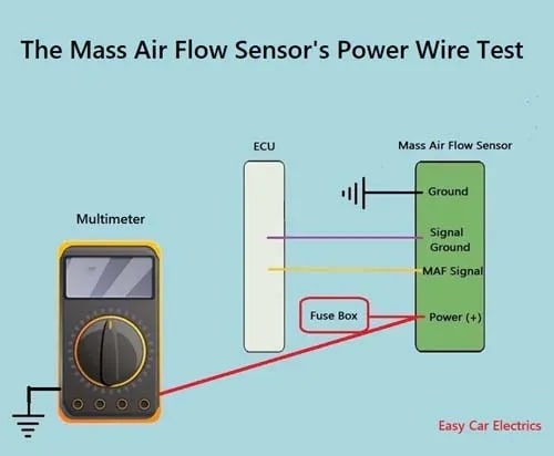
- Check Power:
- Reconnect the negative battery terminal.
- Turn the ignition key to the "ON" position (but do not start the engine).
- Set your multimeter to the DC voltage setting (typically 20V).
- Place the black multimeter lead on a known good ground (e.g., the vehicle chassis).
- Place the red multimeter lead on the power wire of the MAF sensor connector (with the connector still attached to the sensor, if possible – use back-probing techniques).
- You should read approximately 12 volts. If not, check the wiring and the corresponding fuse.
- Check Ground:
- Set your multimeter to the continuity setting (or resistance setting).
- Disconnect the negative battery terminal again.
- Place one multimeter lead on the ground wire of the MAF sensor connector.
- Place the other multimeter lead on a known good ground.
- You should have continuity (a reading of close to 0 ohms) between the ground wire and the vehicle chassis. If not, check the wiring for breaks or corrosion.
- Check Signal Voltage:
- Reconnect the negative battery terminal.
- Set your multimeter to the DC voltage setting (typically 20V).
- Start the engine.
- Place the black multimeter lead on a known good ground.
- Place the red multimeter lead on the signal wire of the MAF sensor connector (using back-probing if necessary).
- At idle, you should see a voltage reading, typically around 0.5 to 1.5 volts. The exact voltage will vary depending on the vehicle.
- Have an assistant slowly increase the engine speed. As the engine speed increases, the voltage reading should also increase smoothly and steadily. A sudden jump or drop in voltage indicates a potential problem with the sensor.
- Dynamic Test (Optional): If you have a scan tool that can read live data, you can also monitor the MAF sensor reading in grams per second (g/s) while the engine is running. Compare the reading to the manufacturer's specifications for your vehicle.
Common Issues and Maintenance Concerns
MAF sensors are susceptible to contamination and damage. Common issues include:
- Contamination: Dust, dirt, oil, and other contaminants can accumulate on the heated element, insulating it and affecting its ability to accurately measure airflow. This is a common issue, especially if the air filter is not properly maintained.
- Damage: The heated element is delicate and can be easily damaged by physical impact or improper cleaning.
- Wiring Problems: Broken or corroded wiring can disrupt the sensor's power, ground, or signal circuits.
- Sensor Failure: Over time, the sensor can simply wear out and fail to function properly.
Regular maintenance, such as replacing the air filter at the recommended intervals, can help to prevent MAF sensor contamination. In some cases, a contaminated MAF sensor can be cleaned with a specialized MAF sensor cleaner. Do not use carb cleaner or other harsh solvents, as these can damage the sensor. Follow the manufacturer's instructions carefully.
Do’s and Don’ts / Best Practices
Here are some do's and don'ts to keep in mind when testing and maintaining your MAF sensor:
- Do: Consult your vehicle's repair manual or wiring diagram for specific information about the MAF sensor and its wiring.
- Do: Use a high-quality multimeter for accurate readings.
- Do: Be careful when handling the MAF sensor, as the heated element is fragile.
- Do: Use back-probing techniques to test the sensor wires without disconnecting the connector, if possible.
- Do: Clean the MAF sensor periodically with a specialized MAF sensor cleaner.
- Don't: Use carb cleaner or other harsh solvents to clean the MAF sensor.
- Don't: Touch the heated element with your fingers or any other object.
- Don't: Assume that a faulty MAF sensor is the only cause of engine performance problems. Other components, such as the oxygen sensors, throttle position sensor, and fuel injectors, can also contribute to similar symptoms.
- Don't: Buy cheap aftermarket MAF sensors. These can be unreliable and may not function properly with your vehicle's ECU. Stick with reputable brands or OEM replacements.
Conclusion
Testing a MAF sensor with a multimeter is a straightforward procedure that can help you diagnose a variety of engine performance problems. By following the steps outlined in this article, you can quickly determine whether the MAF sensor is functioning properly and take the necessary steps to repair or replace it. However, it is essential to remember that a multimeter test is only one part of the diagnostic process. A complete diagnosis may require the use of a scan tool and other diagnostic equipment. If you are not comfortable performing these tests yourself, it is always best to consult a qualified mechanic. But understanding the principles behind MAF sensor operation and basic testing procedures will empower you to communicate more effectively with your mechanic and make informed decisions about your vehicle's repair.