How To Test A Mass Air Flow Sensor
The Mass Air Flow (MAF) sensor is a critical component in modern engine management systems. Understanding how to test it is invaluable for diagnosing performance issues, optimizing engine tuning, and saving money on unnecessary repairs. This article will guide you through the intricacies of MAF sensor testing, providing you with the knowledge and techniques to accurately assess its functionality.
Background: Airflow and Engine Management
To understand the MAF sensor, we must first grasp the basics of engine management. Modern internal combustion engines rely on a precise air-fuel mixture for optimal combustion. The Engine Control Unit (ECU), the "brain" of the engine, controls this mixture by regulating fuel injector pulse width (the duration the injector sprays fuel). But to calculate the correct fuel amount, the ECU must know how much air is entering the engine. This is where the MAF sensor steps in.
Before MAF sensors became commonplace, many vehicles relied on a Manifold Absolute Pressure (MAP) sensor and engine speed (RPM) to estimate airflow. While MAP sensors are still used in some applications, they are generally less accurate than MAF sensors, especially in modified or high-performance engines where airflow characteristics can deviate significantly from the factory calibration. MAF sensors directly measure the mass of air entering the engine, providing the ECU with more precise data for fuel delivery calculations.
Technical Breakdown: How the MAF Sensor Works
The most common type of MAF sensor is the hot-wire or hot-film MAF. Here's how it operates:
- Sensing Element: The sensor contains a heated element, either a thin wire (hot-wire) or a flat film (hot-film), that is exposed to the incoming airflow. This element is usually made of platinum due to its resistance to corrosion and stable electrical properties.
- Heating Circuit: A control circuit constantly heats the sensing element to a specific temperature above the ambient air temperature. This temperature difference is carefully calibrated and maintained by the ECU.
- Airflow Cooling Effect: As air flows across the heated element, it cools it down. The faster the airflow, the greater the cooling effect.
- Current Compensation: The control circuit in the MAF sensor increases the electrical current flowing through the heated element to maintain the target temperature. The amount of current required to compensate for the cooling effect is directly proportional to the mass of air flowing through the sensor.
- Voltage Signal Output: The MAF sensor outputs a voltage signal to the ECU, which represents the amount of current required to maintain the heated element's temperature. This voltage is a direct representation of the mass airflow. Typically, a low voltage (e.g., 0.5V) indicates low airflow (engine at idle), and a higher voltage (e.g., 4.5V) indicates high airflow (engine at wide-open throttle). The specific voltage range will vary depending on the make and model of the vehicle.
- Intake Air Temperature (IAT) Sensor: Many MAF sensors also incorporate an IAT sensor. This sensor measures the temperature of the incoming air. The ECU uses this temperature data to further refine the air-fuel mixture calculation, as air density changes with temperature. The IAT sensor is usually a simple thermistor whose resistance changes with temperature.
In essence, the MAF sensor acts as a sophisticated airflow meter, providing the ECU with real-time data to optimize fuel delivery and ensure efficient combustion. Some newer vehicles are starting to use other types of MAF sensors such as the Karman Vortex sensor but these are far less common than the hot-wire style.
Common Issues and Maintenance Concerns
MAF sensors are exposed to the harsh environment of the intake system and are susceptible to several common problems:
- Contamination: Dust, dirt, oil residue from air filters, and other contaminants can accumulate on the heated element, insulating it and reducing its sensitivity. This can lead to inaccurate readings and performance issues such as rough idling, poor acceleration, and reduced fuel economy.
- Wiring Issues: Damaged or corroded wiring connectors can disrupt the signal from the MAF sensor to the ECU, resulting in intermittent or complete failure.
- Sensor Failure: Over time, the heated element or the internal circuitry of the MAF sensor can fail, leading to inaccurate readings or a complete loss of signal.
- Aftermarket Oiled Air Filters: Oiled air filters, while designed to provide superior filtration, can sometimes deposit oil residue onto the MAF sensor, leading to contamination. Over-oiling can be especially problematic.
- Vacuum Leaks: Vacuum leaks downstream of the MAF sensor (between the MAF and the engine) will introduce unmetered air into the engine. This can confuse the ECU, leading to incorrect fuel trims and drivability problems. While not directly a MAF sensor issue, it can mimic MAF sensor failure.
Regular maintenance, such as cleaning the MAF sensor with a specialized MAF sensor cleaner (more on this later), can help prevent contamination and extend its lifespan. It's also important to ensure that the air filter is properly installed and not over-oiled. Regularly inspect the wiring and connectors for any signs of damage or corrosion.
Testing the MAF Sensor: A Step-by-Step Guide
Before you begin, you'll need a few tools:
- Multimeter: A digital multimeter (DMM) is essential for measuring voltage and resistance.
- OBD-II Scanner: An OBD-II scanner can read diagnostic trouble codes (DTCs) and provide live data from the MAF sensor and other engine sensors. A scanner with live data streaming capability is highly recommended.
- MAF Sensor Cleaner: Use a specialized MAF sensor cleaner. Do not use carburetor cleaner, brake cleaner, or other harsh solvents, as these can damage the delicate sensing element.
- Basic Hand Tools: Screwdrivers, sockets, and wrenches for removing the MAF sensor.
Step 1: Visual Inspection and Diagnostic Trouble Codes (DTCs)
Begin with a visual inspection of the MAF sensor, wiring, and connectors. Look for any signs of damage, corrosion, or loose connections. Then, use an OBD-II scanner to check for any stored DTCs related to the MAF sensor. Common codes include P0100 (MAF Circuit Malfunction), P0101 (MAF Circuit Range/Performance), P0102 (MAF Circuit Low Input), and P0103 (MAF Circuit High Input). Note the codes and their descriptions, as they can provide valuable clues about the nature of the problem. Clear the codes after recording them.
Step 2: Power and Ground Verification
Before assuming the MAF sensor is faulty, verify that it is receiving proper power and ground. Consult your vehicle's wiring diagram to identify the power and ground wires for the MAF sensor. Using a multimeter, perform the following tests with the ignition ON but the engine OFF:
- Power: Check for battery voltage (typically 12V) at the power wire.
- Ground: Check for continuity between the ground wire and a known good ground point on the vehicle chassis. The resistance should be very close to zero ohms.
If either power or ground is missing, troubleshoot the wiring and connectors to identify the source of the problem. A blown fuse, a broken wire, or a corroded connector can all cause a loss of power or ground.
Step 3: Signal Wire Testing (Static Test)
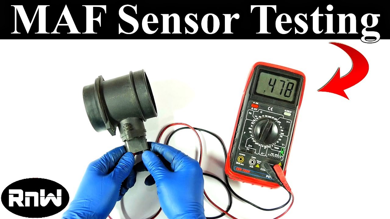
With the ignition ON but the engine OFF, use a multimeter to measure the voltage on the signal wire (output) of the MAF sensor. Refer to your vehicle's service manual for the specific voltage range, but typically it should be around 0.5-1.5V. If the voltage is significantly outside this range, it could indicate a faulty MAF sensor or a wiring problem. This is a static test and only gives a preliminary indication. It's not definitive.
Step 4: Live Data Testing (Dynamic Test)
This is the most crucial test for assessing MAF sensor performance. Start the engine and allow it to reach operating temperature. Using an OBD-II scanner with live data streaming capability, monitor the MAF sensor reading in grams per second (g/s) or pounds per minute (lb/min). Observe the MAF sensor reading at idle and during acceleration.
- Idle Test: At idle, the MAF sensor reading should be within a specific range, typically 2-7 g/s for a 4-cylinder engine and 4-10 g/s for a 6-cylinder engine. The exact values will vary depending on the engine size and other factors. Consult your vehicle's service manual or a reliable online resource for the correct specifications.
- Acceleration Test: Perform a "snap throttle" test by quickly opening the throttle to wide-open throttle (WOT) and then releasing it. The MAF sensor reading should increase rapidly and smoothly as the throttle opens, and then decrease smoothly as the throttle closes. There should be no sudden drops or spikes in the reading. During WOT, the MAF sensor reading should reach a high value, typically 80-150 g/s or more, depending on the engine size and horsepower.
- Compare to Specifications: Compare the observed MAF sensor readings to the manufacturer's specifications. If the readings are significantly outside the expected range, or if the sensor responds erratically to changes in throttle position, it likely indicates a faulty MAF sensor.
Step 5: Cleaning the MAF Sensor (If Necessary)
If the MAF sensor readings are slightly off, but not drastically out of range, try cleaning the sensor before replacing it. Disconnect the MAF sensor from the wiring harness and carefully remove it from the intake system. Spray the sensing element with a specialized MAF sensor cleaner, following the instructions on the can. Do not touch the sensing element with anything, as it is very delicate. Allow the cleaner to evaporate completely before reinstalling the MAF sensor. After cleaning, retest the sensor to see if the readings have improved.
Do's and Don'ts / Best Practices
- DO use a specialized MAF sensor cleaner.
- DO disconnect the battery during any sensor replacement to protect the ECU.
- DO consult your vehicle's service manual for specific voltage ranges and MAF sensor specifications.
- DO replace the air filter regularly to prevent contamination.
- DO check for vacuum leaks if you suspect MAF sensor problems.
- DON'T use carburetor cleaner, brake cleaner, or other harsh solvents to clean the MAF sensor.
- DON'T touch the sensing element with your fingers or any other object.
- DON'T over-oil air filters. If using an oiled filter, follow the manufacturer's instructions carefully.
- DON'T assume that a new MAF sensor will solve all performance problems. Diagnose the root cause of the issue before replacing any parts.
Conclusion
Testing a MAF sensor requires a systematic approach, involving visual inspection, electrical testing, and live data analysis. By following the steps outlined in this article, you can accurately assess the functionality of your MAF sensor and diagnose any potential problems. If the MAF sensor fails any of the tests, and cleaning doesn't resolve the issue, replacement is the recommended course of action. Remember to always consult your vehicle's service manual for specific specifications and procedures. With patience and attention to detail, you can effectively troubleshoot MAF sensor issues and keep your engine running smoothly.