How To Turn On My Fog Lights
So, you're having a little trouble getting your fog lights to fire up, eh? Or maybe you're just curious about the electrical dance happening behind the dashboard when you flick that switch. Either way, understanding your fog light circuit is a valuable skill for any serious DIYer. This isn't just about replacing a bulb; it's about diagnosing electrical problems, potentially modifying your system (safely!), and generally gaining a deeper understanding of your vehicle's inner workings.
Purpose of Understanding the Fog Light Circuit
Having a grasp of the fog light circuit diagram is crucial for a number of reasons. Firstly, for repairs. When your fog lights aren't working, tracing the circuit allows you to pinpoint the fault, whether it's a blown fuse, a faulty relay, a bad switch, or a broken wire. Secondly, for modifications. Thinking about adding LED fog lights or integrating them into a custom lighting system? Understanding the circuit is essential to ensure proper wiring and avoid overloading the system. Finally, for general knowledge. Even if everything's working fine, understanding the diagram is an excellent exercise in understanding automotive electrical systems, making you a more competent and confident DIY mechanic.
Key Specs and Main Parts
The fog light circuit, while seemingly simple, relies on several key components working in harmony. Let's break them down:
- Battery (12V DC): The heart of the electrical system, providing the necessary power.
- Fuse: A sacrificial element designed to protect the circuit from overcurrent. A blown fuse is often the first sign of a problem. Typical fog light fuse amperage ranges from 10A to 20A, depending on the vehicle and the power consumption of the fog lights.
- Relay: An electrically operated switch. The fog light switch controls a small current that activates the relay, which then allows a larger current to flow to the fog lights. This protects the switch from damage. A typical fog light relay might be rated for 30A.
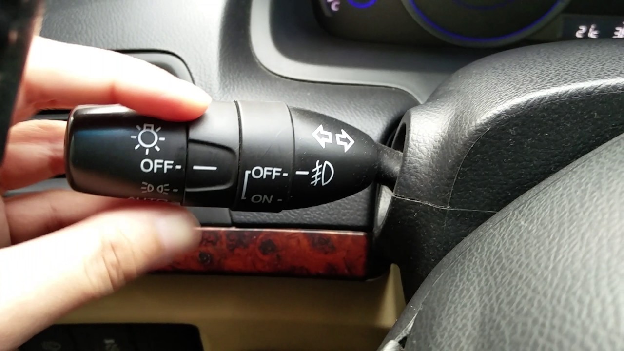
- Fog Light Switch: Controls the relay, initiating the fog light operation. This switch is usually located on the dashboard or the steering column.
- Fog Lights (Lamps): The actual lights themselves. These can be halogen, LED, or HID (High-Intensity Discharge). The wattage of the fog lights will determine the overall current draw of the circuit.
- Wiring Harness: The network of wires connecting all the components. Wire gauge is important; it must be thick enough to handle the current without overheating. 16-gauge wire is commonly used, but larger gauge wire (e.g., 14-gauge) may be necessary for higher-wattage lights.
- Ground Connection: Crucially important! Provides the return path for the current back to the battery. A poor ground connection is a common cause of electrical problems.
Understanding the Symbols in the Diagram
Electrical diagrams use a standardized set of symbols to represent components and connections. Getting familiar with these symbols is key to interpreting the diagram effectively. Here's a breakdown of the common symbols you'll encounter in a fog light circuit diagram:
- Solid Lines: Represent wires connecting the components. The thickness of the line doesn't necessarily indicate wire gauge, but sometimes heavier lines indicate higher current carrying capacity.
- Dashed Lines: Can represent optional or less critical connections. Sometimes they're used to indicate a ground connection to the vehicle chassis.
- Circles with a "+" or "-": Indicate the battery terminals (positive and negative).
- Rectangle with a jagged line through it: Represents a resistor, which limits current flow. You likely won't see this directly in a basic fog light circuit, but may encounter it in more complex lighting setups.
- Zigzag Line within a circle: Represents a light bulb or lamp.
- Square with a coil symbol inside: Represents a relay. The coil is the electromagnet that actuates the switch.
- Stair-step symbol: This depicts the ground connection to the frame.
- Different Colors: Wire colors are often indicated next to the lines representing the wires. This is extremely helpful for tracing wires in the real world. Common colors include red (power), black (ground), and yellow (switch signal).
How It Works: The Fog Light Circuit Explained
Let's walk through the fog light circuit step-by-step:
- Power Supply: The circuit begins with the battery. A positive cable runs from the battery to the fuse box.
- Fuse Protection: The power then flows through the fog light fuse. This protects the circuit from overloads. If the current exceeds the fuse rating, the fuse blows, interrupting the circuit.
- Relay Activation: From the fuse, the power goes to one side of the relay's coil. The other side of the relay's coil is connected to the fog light switch.
- Switch Control: When you turn on the fog light switch, it completes the circuit to ground for the relay coil. This energizes the electromagnet inside the relay.
- Relay Switching: When the relay coil is energized, it pulls the relay's contacts together, completing the high-current circuit. This allows power to flow from the battery, through the relay's contacts, and to the fog lights.
- Illumination: The power flows through the wiring harness to the fog lights, causing them to illuminate.
- Ground Return: Finally, the current returns to the battery through the ground wires connected to the fog lights and the vehicle's chassis.
Real-World Use: Basic Troubleshooting Tips
Okay, so your fog lights aren't working. What do you do? Here's a basic troubleshooting guide:
- Check the Fuse: This is the first and easiest step. Use a multimeter to check for continuity across the fuse. If it's blown, replace it with a fuse of the same amperage.
- Check the Bulbs: Obvious, but often overlooked. Are the fog light bulbs burned out? Replace them with the correct type and wattage.
- Check the Relay: You can test the relay by swapping it with a known good relay (if you have one). You can also use a multimeter to check for continuity across the relay's contacts when the relay is activated. You should hear a "click" when the relay activates.
- Check the Switch: Use a multimeter to check if the switch is providing power when turned on.
- Check the Wiring: Look for any signs of damage to the wiring harness, such as frayed wires, corroded connectors, or loose connections. Use a multimeter to check for continuity in the wires.
- Check the Ground Connections: Ensure that the ground connections are clean and secure. Clean any corrosion and tighten the connections. A bad ground can cause all sorts of weird electrical problems.
Safety: Working with Automotive Electrical Systems
Working with automotive electrical systems can be dangerous. Here are some important safety precautions:
- Disconnect the Battery: Always disconnect the negative battery terminal before working on any electrical system. This will prevent accidental shorts and shocks.
- Use Proper Tools: Use insulated tools designed for automotive electrical work.
- Be Careful with High-Current Circuits: The battery can deliver a lot of current, so be careful not to create any shorts.
- Work in a Well-Ventilated Area: Some automotive fluids and materials can be flammable or toxic.
- Never Work Alone: It's always a good idea to have someone else present in case of an emergency.
Remember, the battery, the wiring harness, and any exposed connections are potential hazards. Always exercise caution and double-check your work.
Hopefully, this explanation of the fog light circuit has been helpful. By understanding the components, the symbols, and the flow of electricity, you can confidently diagnose and repair problems with your fog lights. Happy wrenching!
We have a sample fog light circuit diagram available for download. This diagram is a generic representation and may not perfectly match your vehicle's specific wiring, but it will provide a valuable visual aid to understanding the circuit. Contact us, and we can provide this file for your reference.