How To Turn On Your Fog Lights
Let's dive into the often-overlooked, but crucially important, world of fog lights. This article will walk you through understanding how your fog light system works, how to diagnose common issues, and what all those squiggly lines and symbols mean on your vehicle's electrical diagram. Consider this your comprehensive guide to understanding and maintaining your fog lights.
Why Understand Your Fog Light System?
Knowing your way around your fog light system is beneficial for several reasons. Not only does it empower you to perform your own basic troubleshooting and repairs (saving you money and time), but it also deepens your understanding of your vehicle's overall electrical architecture. This knowledge is particularly helpful if you're planning any aftermarket modifications, like adding auxiliary lighting or upgrading your existing fog lights. Understanding the schematic allows you to integrate aftermarket components safely and effectively, avoiding potential electrical problems. Plus, understanding the system helps you to accurately diagnose and fix problems like a fog lamp that won't turn on.
Key Specs and Main Parts of a Fog Light System
A typical fog light system, while seemingly simple, consists of several key components working in harmony:
- Fog Lights (Lamps): These are the actual light fixtures designed to project a wide, low beam of light, minimizing glare in foggy conditions. They typically use halogen, LED, or HID (High-Intensity Discharge) bulbs. Wattage is a key specification here, often ranging from 35W to 55W for halogen, and lower for LEDs.
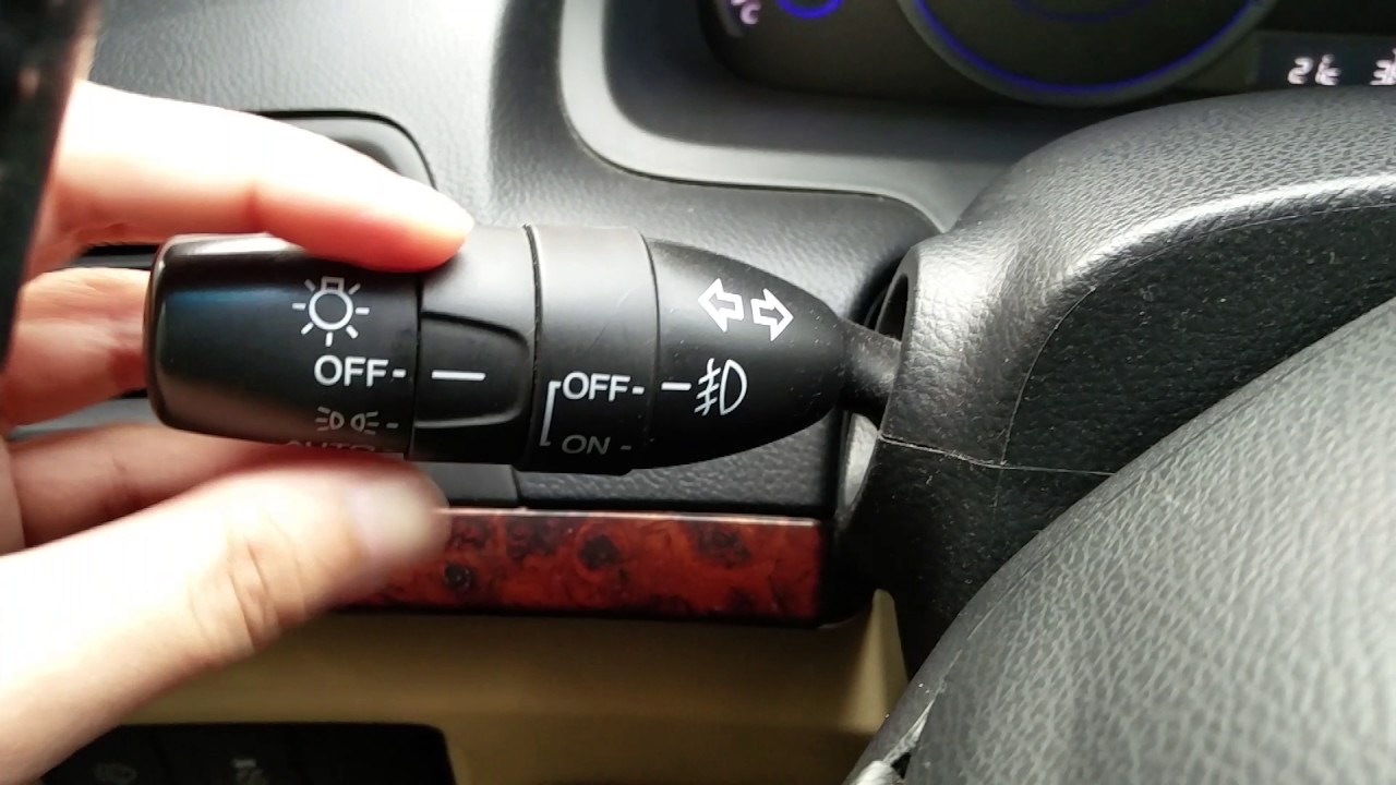
- Switch: This is the driver interface for activating and deactivating the fog lights. It could be a dedicated switch on the dashboard, or integrated into the headlight switch stalk.
- Relay: A relay is an electrically operated switch that uses a small current to control a larger current. In the fog light system, the relay allows a low-current signal from the switch to control the high-current power flow to the fog lights. This protects the switch from damage. Look for specifications like contact rating (e.g., 20A, 30A) which indicates the maximum current the relay can handle.
- Fuse: The fuse is a safety device designed to protect the electrical circuit from overcurrent. It contains a thin wire that melts and breaks the circuit if the current exceeds a specified limit. Fuses are rated in amperes (A), and using the correct amperage fuse is critical.
- Wiring Harness: The wiring harness is the network of wires that connects all the components of the fog light system. Wire gauge (thickness) is important, as it determines how much current the wire can safely carry. Thicker wires (lower gauge numbers) can carry more current.
- Ground Connection: A good ground connection is essential for any electrical circuit. This provides a return path for the current to the vehicle's chassis, completing the circuit.
Decoding the Electrical Diagram: Symbols, Lines, and Colors
Electrical diagrams are essentially visual roadmaps of an electrical circuit. Understanding the symbols and conventions used is crucial for interpreting them correctly.
- Wires (Lines): Solid lines represent wires. Dashed lines may indicate wires that are optional or part of a different circuit. The thickness of the line usually does *not* represent the wire gauge.
- Components (Symbols):
- Resistor: Zig-zag line.
- Capacitor: Two parallel lines.
- Inductor: Coiled line.
- Diode: Triangle pointing to a vertical line.
- Switch: A line bridging two points, often with an arrow indicating the direction of movement.
- Relay: A coil symbol connected to a switch symbol. The coil represents the relay's electromagnet, and the switch represents the contacts that open or close the circuit.
- Fuse: A squiggly line inside a rectangle, or sometimes just a rectangle with the amperage rating inside.
- Ground: A series of downward-pointing lines or a triangle pointing downwards.
- Light Bulb: A circle with an 'X' inside.
- Colors: Wire colors are usually indicated on the diagram using abbreviations (e.g., BLK for black, RED for red, GRN for green, YEL for yellow, BLU for blue, WHT for white). These colors are crucial for identifying specific wires in the harness.
- Numbers/Labels: Each wire and component is usually labeled with a number or code that corresponds to a legend on the diagram. This helps you identify the function of each element.
Example: A line labeled "12V RED" indicates a 12-volt wire that is red in color. A symbol labeled "F10 (15A)" indicates a fuse labeled F10 with a 15-ampere rating.
How the Fog Light System Works: A Simplified Explanation
Here's a breakdown of the typical fog light system's operation:
- Activation: When you turn on the fog light switch, it sends a low-current signal to the relay coil.
- Relay Engagement: The low-current signal energizes the relay coil, creating an electromagnetic field that pulls the relay's switch contacts closed.
- Power Delivery: With the relay contacts closed, a high-current circuit is completed, allowing power to flow from the battery (typically through a fuse) to the fog lights.
- Illumination: The fog lights receive power and illuminate, providing enhanced visibility in foggy or adverse weather conditions.
- Deactivation: When you turn off the fog light switch, the relay coil is de-energized, the relay contacts open, and the power to the fog lights is cut off.
Real-World Troubleshooting: Common Issues and Solutions
Here are some common fog light problems and how to diagnose them using your newfound knowledge:
- Fog Lights Don't Turn On At All:
- Check the Fuse: This is always the first step. Use a multimeter in continuity mode to check if the fuse is blown. Replace it with a fuse of the same amperage rating.
- Check the Bulbs: Visually inspect the bulbs for a broken filament. Use a multimeter to check for continuity across the bulb terminals.
- Check the Relay: You can test the relay by swapping it with a known good relay (if you have one). You can also use a multimeter to check for voltage at the relay terminals when the fog light switch is activated. If there's no voltage, the switch or wiring to the relay may be faulty.
- Check the Switch: Use a multimeter to check for continuity across the switch terminals when the switch is in the "on" position. If there's no continuity, the switch is faulty.
- Check Ground Connections: Ensure the ground connection is clean and tight. Corrosion can prevent a good ground. Use sandpaper to clean the connection point.
- One Fog Light Works, the Other Doesn't:
- Check the Bulb: Most likely, the bulb is burned out.
- Check the Wiring: Inspect the wiring to the non-working fog light for damage or loose connections. Use a multimeter to check for voltage at the fog light connector.
- Fog Lights Turn On But Are Dim:
- Check Ground Connections: A poor ground connection is a common cause of dim lights.
- Check Voltage Drop: Use a multimeter to measure the voltage at the fog light connector. If the voltage is significantly lower than the battery voltage, there may be excessive resistance in the wiring.
Safety First: Handling Electrical Components
Working with automotive electrical systems can be dangerous if you don't take proper precautions:
- Disconnect the Battery: Always disconnect the negative battery terminal before working on any electrical system. This will prevent accidental shorts and potential electrical shocks.
- Work in a Well-Lit Area: Good lighting is essential for seeing what you're doing and avoiding mistakes.
- Use Proper Tools: Use insulated tools designed for automotive electrical work.
- Don't Overload Circuits: Never install a fuse with a higher amperage rating than specified. This can damage the wiring and create a fire hazard.
- Respect Capacitors: Capacitors can store electrical charge even after the battery is disconnected. Be careful when handling capacitors, especially in older vehicles.
High-Intensity Discharge (HID) systems: HID systems operate at very high voltages and can pose a serious shock hazard. If you're working on an HID system, it's best to have it serviced by a qualified technician.
By understanding the components, symbols, and operation of your fog light system, you can confidently diagnose and repair common issues, ensuring safe and reliable operation. We have a detailed fog light wiring diagram available for download. This diagram provides a comprehensive overview of the fog light circuit and can be an invaluable resource for troubleshooting and repairs.