How To Use A Charging Station
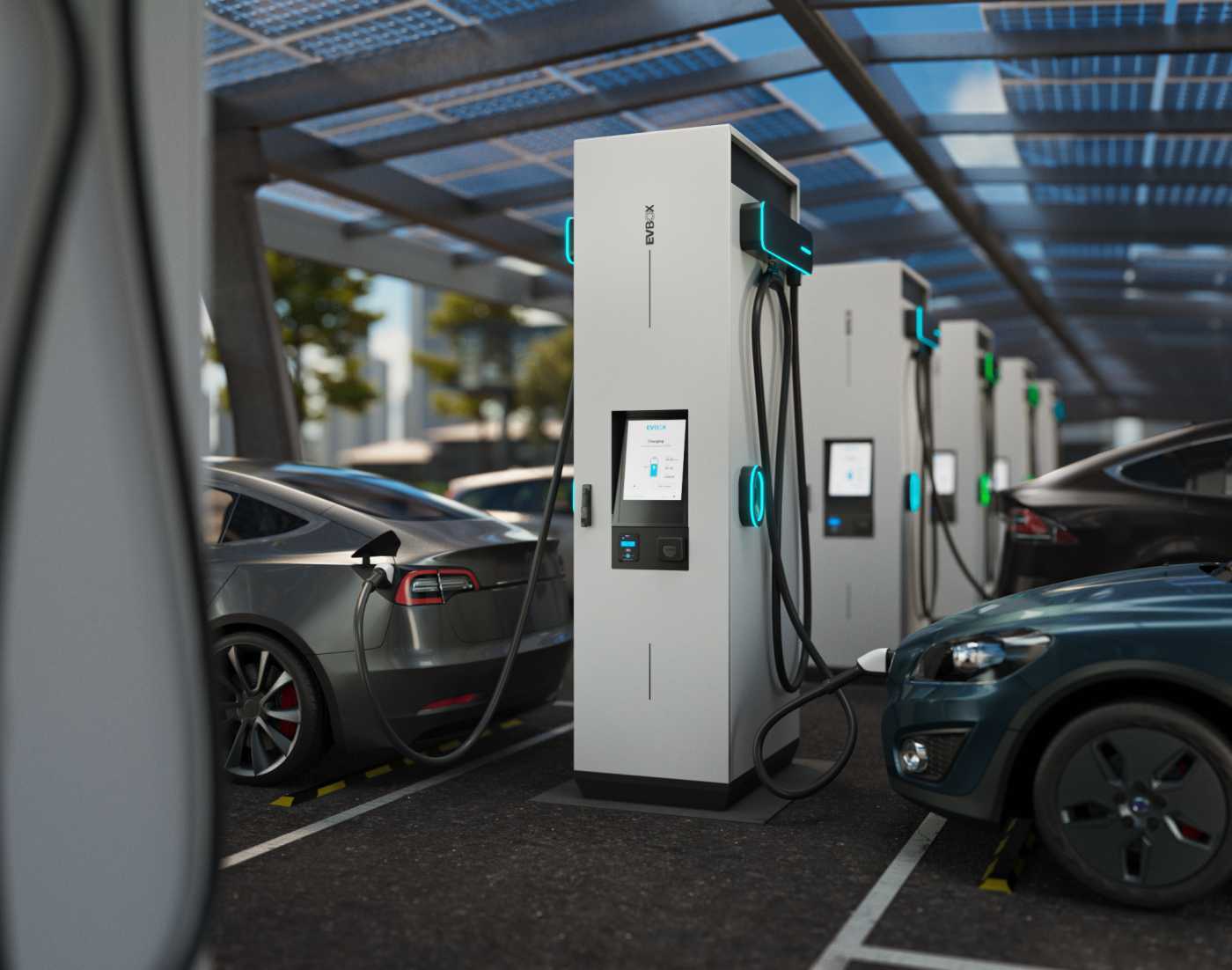
Alright, let's dive into the world of EV charging stations. Whether you're considering installing one at home, working on maintaining an existing setup, or simply want a deeper understanding of how your electric vehicle gets its juice, this breakdown is for you. We'll explore the inner workings of a charging station using a detailed schematic, which we'll refer to throughout this article. Think of it as a roadmap to understanding the charging process.
Purpose of Understanding Charging Station Schematics
Why bother learning about charging station diagrams? Several compelling reasons exist:
- DIY Repairs & Maintenance: Identifying faulty components becomes significantly easier with a schematic. You can trace circuits, check voltages, and pinpoint issues faster than randomly probing around.
- Upgrades & Modifications: Considering adding a smart charging module or beefing up the current capacity? A schematic is vital to ensure compatibility and avoid damaging the existing system.
- Troubleshooting: Knowing the flow of electricity and the function of each component is crucial for diagnosing charging problems, whether at home or on the road.
- Knowledge & Understanding: Even if you don't plan to do hands-on work, understanding the technology powering your EV enhances your overall ownership experience.
Key Specs and Main Parts
Before we dissect the diagram, let's familiarize ourselves with the core components and their specifications:
- Input Power: This is the electrical supply feeding the charging station. It's typically specified as voltage (e.g., 240V AC for Level 2 charging) and amperage (e.g., 30A, 40A, 50A). The input power dictates the charging station's maximum output.
- Main Circuit Breaker: A crucial safety device that protects the charging station and your home's electrical system from overloads and short circuits. It's rated in amps and breaks the circuit when the current exceeds its rating.
- Contactor: This is an electrically controlled switch that allows the charging station to safely turn on and off the high-voltage power flow to the vehicle. It's a heavy-duty relay.
- Charging Cable (EVSE Cable): The physical cable connecting the charging station to the vehicle. It must be appropriately rated for the voltage and current.
- Connector (J1772 or CCS): The physical interface that plugs into the vehicle. J1772 is the standard for Level 1 and Level 2 charging in North America, while CCS (Combined Charging System) adds DC fast charging capabilities.
- Control Pilot Circuit: This is the "brain" of the charging station. It communicates with the vehicle to determine the maximum charging current available, initiates charging, and monitors safety parameters.
- Ground Fault Circuit Interrupter (GFCI): A vital safety feature that detects current leakage to ground and quickly cuts off power to prevent electric shock.
- Metering (Optional): Some charging stations include a meter to track energy consumption for billing or monitoring purposes.
- Smart Charging Module (Optional): Enables features like remote control, scheduled charging, and energy management via a network connection (Wi-Fi or Ethernet).
Understanding the Symbols
Charging station schematics, like any electrical diagram, use standard symbols to represent components and connections. Here's a breakdown of common symbols you'll encounter:
- Lines:
- Solid Lines: Represent conductive wires carrying electrical current.
- Dashed Lines: Typically indicate control signals or communication lines.
- Lines with Arrows: Illustrate the direction of current flow.
- Colors:
- Black/Brown: Usually represents the "hot" or live wire carrying the voltage.
- White/Gray: Represents the neutral wire, which completes the circuit.
- Green/Green with Yellow Stripe: Represents the ground wire, which provides a safe path for fault current.
- Component Symbols:
- Resistor: A zig-zag line.
- Capacitor: Two parallel lines.
- Diode: A triangle pointing to a line.
- Transistor: A more complex symbol with three legs, indicating a switching or amplifying function.
- Relay/Contactor: A coil with a switch symbol.
- Fuse/Circuit Breaker: A line with a squiggle through it.
- Ground: Three horizontal lines getting progressively smaller.
- Connector Symbols: These vary, but often show interlocking shapes representing the male and female connectors.
How It Works: The Charging Process
Let's trace the path of electricity from the power grid to your EV:
- Power Input: AC power enters the charging station from your home's electrical panel.
- Circuit Breaker Protection: The main circuit breaker protects the charging station and your home's wiring from overloads.
- Contactor Control: The control pilot circuit signals the contactor to close, allowing power to flow to the charging cable. The contactor only closes if the EV is properly connected and ready to charge.
- Control Pilot Communication: The EVSE (Electric Vehicle Supply Equipment) communicates with the vehicle's on-board charger via the control pilot signal. This signal dictates the maximum charging current that the EV can draw. This is crucial for safety and prevents overloading the circuit.
- GFCI Protection: The GFCI continuously monitors for ground faults. If it detects a leakage current, it immediately trips the contactor, cutting off power to the cable.
- AC to DC Conversion (Onboard Charger): The vehicle's onboard charger converts the AC power from the charging station into DC power suitable for charging the battery. Note: the charging station for Level 1 and Level 2 AC charging does not perform AC to DC conversion. This conversion takes place inside the vehicle. DC Fast Chargers (Level 3) perform the AC to DC conversion in the charging station itself.
- Battery Charging: The DC power is then used to charge the battery.
Real-World Use: Basic Troubleshooting Tips
Here are a few common issues you might encounter and how to troubleshoot them:
- Charging Station Not Powering On: Check the circuit breaker in your home's electrical panel. If tripped, reset it. If it trips again immediately, there's likely a short circuit. Inspect the charging station's wiring and components for damage. Also, check the input voltage with a multimeter to ensure it's within the expected range.
- Charging Starts, Then Stops: This could be due to overheating. Many charging stations have thermal protection that will shut them down if they get too hot. Ensure the charging station has adequate ventilation. Also, check the charging cable and connector for damage or corrosion.
- Vehicle Not Recognizing Charging Station: Ensure the charging cable is fully seated in both the charging station and the vehicle. Clean the connector pins if necessary. There could also be a problem with the control pilot circuit. A diagnostic tool that can read EV charging codes may be necessary.
- GFCI Tripping: This indicates a ground fault. Disconnect the charging station and carefully inspect the wiring for any damaged insulation or exposed wires. Do not attempt to fix a ground fault unless you are a qualified electrician.
Safety First: Risky Components
Working with electricity is inherently dangerous. Here are the most critical safety precautions to observe:
- High Voltage: Charging stations operate at potentially lethal voltages (typically 240V AC). Always disconnect the charging station from the power source before working on it. Turn off the breaker in your main panel.
- Capacitors: Capacitors store electrical energy even after the power is disconnected. Discharge them carefully before touching them. Use a resistor to safely discharge the capacitor.
- Ground Faults: A ground fault can create a shock hazard. If the GFCI trips repeatedly, do not attempt to bypass it. Instead, have a qualified electrician diagnose and repair the problem.
- Wiring: Use only properly rated wiring and connectors. Incorrect wiring can lead to overheating, fires, and electrical shocks.
- Qualified Personnel: If you're not comfortable working with electricity, always consult a qualified electrician. Incorrect repairs can be dangerous and could void warranties.
This guide provides a foundational understanding of EV charging station schematics and operation. Remember, safety is paramount. Always prioritize safety precautions and consult with qualified professionals when needed.
We have the complete charging station schematic file available for download. This detailed document provides a comprehensive overview of the charging station's internal workings, including component specifications, circuit diagrams, and troubleshooting procedures. Use this to aid your study and future endeavors.