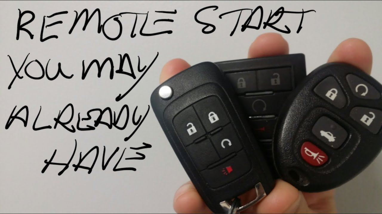
How To Use My Remote Start
So, you've got a remote start system installed, or maybe you're considering upgrading. Either way, understanding how it works under the hood is crucial, whether it's for basic troubleshooting, performing repairs, or just satisfying your curiosity about your car's inner workings. This guide dives deep into the operation of a typical aftermarket remote start system, providing you with the knowledge to confidently diagnose issues and appreciate the technology that lets you preheat your car on a frosty morning.
Understanding the Remote Start Diagram: Your Key to Control
This document serves as your roadmap to the remote start system's electrical circuitry. By understanding the wiring diagram, you can effectively troubleshoot issues, identify faulty components, and even make informed modifications or upgrades. We'll break down the common symbols, key components, and how everything interacts to bring your engine to life from a distance.
Purpose: This diagram is essential for diagnosing remote start problems, tracing wiring issues, understanding the interaction between the remote start module and the vehicle's electrical system, and planning for potential upgrades or modifications to the system.
Key Specs and Main Parts of a Remote Start System
Before we dive into the diagram, let's outline the core components and specifications commonly found in aftermarket remote start systems:
Core Components:
- Remote Start Module (RSM): This is the brain of the operation. It receives the signal from the remote and orchestrates the entire starting sequence. The RSM usually houses a microcontroller, relays, and various input/output (I/O) connections.
- Remote Transmitter (Fob): The handheld device that sends the start, stop, and sometimes lock/unlock commands to the RSM. Fobs typically operate on specific radio frequencies (e.g., 433 MHz, 900 MHz).
- Antenna: Receives the signal transmitted from the remote fob and relays it to the RSM. Antenna placement is crucial for optimal range.
- Hood Pin Switch: A safety device that prevents remote starting if the hood is open. This prevents accidental starting while someone is working on the engine.
- Brake Switch Input: Disables the remote start if the brake pedal is pressed. This is a critical safety feature.
- Tachometer Input (or Virtual Tach): The RSM needs to know the engine RPM to ensure a successful start and prevent over-revving. This signal is often sourced directly from the tachometer wire (analog tach) or through a more complex data bus interface (virtual tach).
- Ignition Wires: These wires connect to the vehicle's ignition system, mimicking the action of turning the key in the ignition. Common wires include:
- Ignition 1 & 2: Supplies power to the ignition system during cranking and running.
- Accessory: Powers accessories like the radio and climate control.
- Starter: Activates the starter motor to crank the engine.
- Parking Light Output: Flashes the parking lights to indicate that the remote start has been activated or the engine is running.
- Door Lock/Unlock Outputs (Optional): Some systems integrate with the vehicle's door locking system.
Key Specifications:
- Operating Voltage: Typically 12V DC (matching the vehicle's electrical system).
- Current Consumption: Varies depending on the system and whether it's in standby or active mode. This is important for assessing the drain on the vehicle's battery.
- Operating Temperature Range: Important for cold-weather performance.
- Remote Range: The maximum distance the remote can reliably communicate with the RSM.
- Frequency: Radio frequency on which the remote operates (e.g., 433 MHz, 900 MHz).
Decoding the Wiring Diagram: Symbols, Lines, and Colors
A wiring diagram is a symbolic representation of the electrical connections within the remote start system and its integration with the vehicle's electrical system. Understanding the symbols is key to interpreting the diagram:
- Lines: Solid lines represent wires, while dashed lines often indicate optional connections or wires that are part of a data bus. The thickness of the line doesn't necessarily indicate wire gauge, but rather, it improves visual clarity.
- Colors: Wires are typically color-coded (e.g., red for power, black for ground). The diagram will often use the same color scheme as the actual wires in the system, making identification easier. Refer to the color code legend on the diagram.
- Symbols: Common symbols include:
- Resistors: A squiggly line.
- Capacitors: Two parallel lines.
- Diodes: A triangle pointing to a line.
- Relays: A coil symbol with switch contacts. Relays are crucial for switching high-current circuits using a low-current signal from the RSM.
- Fuses: A line with a break in the middle, often enclosed in a rectangle.
- Ground: A series of lines decreasing in length.
- Connectors: Circles or squares where wires connect.
Pay close attention to the wire gauge (AWG – American Wire Gauge) specified in the diagram. Using a wire gauge that is too small can lead to overheating and potential fire hazards.
How Remote Start Systems Work: The Starting Sequence
Here's a breakdown of the remote start process, step-by-step:
- Remote Activation: You press the start button on the remote fob.
- Signal Transmission: The remote transmits a coded radio frequency signal to the antenna.
- Signal Reception: The antenna receives the signal and relays it to the RSM.
- Security Check: The RSM verifies the received code to ensure it's a valid command. This prevents unauthorized starting.
- System Readiness Check: The RSM checks safety inputs, such as the hood pin switch and brake switch. If either is active (hood open or brake pedal pressed), the start sequence is aborted.
- Ignition Activation: The RSM activates the appropriate ignition wires (Ignition 1, Ignition 2, Accessory) via its internal relays, mimicking the turning of the ignition key to the "ON" position.
- Starter Activation: The RSM activates the starter wire via a relay to crank the engine. The duration of the cranking is determined by the RSM, typically based on the tachometer input or a pre-programmed timer.
- Engine Running Verification: The RSM monitors the tachometer input (or virtual tach data) to verify that the engine has started. If the engine doesn't start within a predetermined time, the RSM will typically attempt to crank the engine again a few times.
- Parking Light Confirmation: The RSM activates the parking light output to flash the lights, indicating that the remote start was successful and the engine is running.
Real-World Use: Basic Troubleshooting Tips
Even with a solid understanding of the system, things can still go wrong. Here are some common issues and how to approach them:
- Remote Start Doesn't Work:
- Check the Battery: Ensure the remote fob has fresh batteries.
- Check the Range: Try starting the car from closer range.
- Verify Hood Pin Switch: Make sure the hood is securely closed and the hood pin switch is functioning correctly.
- Check Fuses: Inspect the remote start system's fuses and the vehicle's fuses related to the ignition system.
- Security System Interference: If the vehicle has an aftermarket alarm system, it might be interfering with the remote start.
- Engine Cranks But Doesn't Start:
- Tachometer Input: Ensure the tachometer input is properly connected and providing an accurate signal to the RSM. A weak or missing tach signal can prevent the RSM from properly timing the starter activation.
- Fuel Delivery: The remote start system might be interfering with the vehicle's fuel delivery system. This is less common but possible.
- Engine Starts and Immediately Shuts Off:
- Security System: The vehicle's anti-theft system might be disabling the engine.
- Tachometer Signal: An inaccurate tachometer signal can cause the engine to shut off prematurely.
- Parking Lights Don't Flash:
- Parking Light Output: Check the wiring and connections to the parking light output wire from the RSM.
- Blown Fuse: Check the fuse associated with the parking lights.
Safety First: Handle with Care
Working with automotive electrical systems can be dangerous. Here are some key safety precautions:
- Disconnect the Battery: Always disconnect the negative battery terminal before working on the electrical system. This prevents accidental shorts and potential damage to the system or injury.
- Proper Wiring Techniques: Use proper crimping and soldering techniques to ensure secure and reliable connections. Poor connections can lead to electrical issues and even fires.
- Fuse Protection: Ensure all circuits are properly fused to protect against overcurrent conditions.
- Avoid Cutting Factory Wires: Whenever possible, use T-taps or wire taps to connect to existing wires. Cutting factory wires can void your vehicle's warranty and make it difficult to revert to the original configuration.
- Airbags and SRS: Be extremely cautious when working near airbags or the Supplemental Restraint System (SRS). Disconnecting or tampering with these systems can be dangerous and could result in accidental airbag deployment.
Warning: The starter circuit carries a very high current. Incorrect wiring or faulty relays in this circuit can lead to overheating and potential fire hazards. Always use appropriately sized wiring and ensure relays are rated for the required current. Improperly installed systems can also bypass critical safety features, potentially allowing the vehicle to be started while in gear.
Remember, this guide is intended for informational purposes and assumes a basic understanding of automotive electrical systems. If you're not comfortable working with electrical wiring, it's always best to consult a qualified professional.
We have a detailed wiring diagram available for download. This diagram provides a visual representation of the remote start system's connections and can be a valuable tool for troubleshooting and understanding your system. Contact us through the email provided to receive the file.