How To Wire An Ignition Coil Diagram
Understanding and correctly wiring an ignition coil is crucial for reliable engine operation. Whether you're diagnosing a no-start condition, upgrading your ignition system, or undertaking a classic car restoration, knowing the ins and outs of coil wiring can save you time, money, and potential headaches. This article will provide a technical yet approachable guide to wiring ignition coils, assuming you already have a basic understanding of automotive electrical systems.
A Quick Dive into Ignition System Fundamentals
Before we get into the specifics of wiring, let's establish some background on the ignition system. In an internal combustion engine, the air-fuel mixture within the cylinders needs to be ignited to create the power that drives the pistons. This ignition is achieved by a spark plug, which produces an electrical arc. However, the voltage required to jump the gap in a spark plug (typically 10,000 to 25,000 volts or more) is far higher than the standard 12 volts supplied by a car's battery. This is where the ignition coil comes in.
The ignition coil is essentially a step-up transformer. It takes the relatively low voltage from the battery and dramatically increases it to a level sufficient to create a spark at the spark plug. Older vehicles often used a single coil to serve all cylinders via a distributor. Modern vehicles almost universally employ coil-on-plug (COP) or coil-near-plug (CNP) systems, where each cylinder has its own dedicated ignition coil. This eliminates the need for a distributor and allows for more precise timing and greater spark energy.
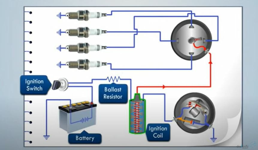
Distributor-Based Systems: A Legacy
In older, distributor-based systems, the ignition coil typically had two main terminals: a primary terminal (often marked "+" or "BAT") connected to the ignition switch and battery positive, and a secondary terminal (the high-voltage output) connected to the distributor cap. The distributor then sequentially routed the high-voltage spark to the correct spark plug at the appropriate time in the engine's firing order. The distributor contains a rotor that spins inside the cap, contacting each terminal inside the cap, one for each cylinder.
Coil-On-Plug (COP) and Coil-Near-Plug (CNP) Systems: Modern Precision
COP and CNP systems offer increased efficiency and reliability. In COP systems, the ignition coil sits directly atop the spark plug. CNP systems are similar, but the coil is located close to the spark plug and connected via a short spark plug wire. These systems generally have three or four wires connected to the coil:
- Power (12V): Supplies the coil with the necessary voltage.
- Ground: Provides the electrical return path.
- Trigger (Signal): This is the control signal from the engine control unit (ECU) that tells the coil when to fire. The ECU rapidly switches this signal on and off, causing the magnetic field in the coil to collapse and generate the high-voltage spark.
Wiring Diagram Breakdown: The How-To
Let's break down the wiring of a modern COP/CNP ignition coil. Although the number of wires and their colors may vary depending on the vehicle manufacturer and specific engine, the underlying principles remain the same.
- Identifying the Terminals: The first step is to correctly identify each terminal on the ignition coil connector. Consult your vehicle's wiring diagram for precise information. If you don't have a wiring diagram, try searching online using your vehicle's make, model, and year, along with the keywords "ignition coil wiring diagram."
- Power Wire: This wire provides the 12-volt power supply to the coil. It's typically connected to the ignition switch, so it only receives power when the ignition is turned on. Use a multimeter to verify that this wire has 12 volts when the ignition is in the "ON" position.
- Ground Wire: This wire provides the ground connection for the coil. It's essential for completing the electrical circuit. Ensure that the ground connection is clean and secure. A poor ground can cause weak spark, misfires, and even coil damage. Using a multimeter, verify continuity between this wire and the vehicle's chassis ground.
- Trigger (Signal) Wire: This wire carries the signal from the ECU that controls when the coil fires. The ECU rapidly switches this signal between 0 volts and 5 volts (or 12 volts in some older systems). This rapid switching causes the magnetic field within the coil to collapse, generating the high-voltage spark.
Wiring Diagram Example (Generic 4-Wire COP Coil):
While every vehicle is different, here's a common wiring scenario:
- Pin 1: 12V Power (Typically Red or Red/White)
- Pin 2: Ground (Typically Black or Brown)
- Pin 3: Trigger Signal from ECU (Color Varies - Refer to Wiring Diagram)
- Pin 4: Not Used (or possibly a diagnostic signal)
Note: Always consult the specific wiring diagram for your vehicle. Using the wrong wiring can damage the coil, the ECU, or other components.
Common Ignition Coil Issues and Maintenance
Ignition coils are subjected to high temperatures and electrical stress, making them prone to failure over time. Here are some common issues:
- Cracked Housing: Heat and vibration can cause the coil housing to crack, allowing moisture to enter and short circuit the coil.
- Internal Short Circuits: Overheating and electrical stress can cause internal short circuits, reducing the coil's output voltage.
- Weak Spark: A weak spark can result from a worn-out coil, poor wiring connections, or a faulty ECU.
- Misfires: Misfires occur when the spark plug fails to ignite the air-fuel mixture in the cylinder. This can be caused by a faulty ignition coil, worn spark plugs, or other engine problems.
Maintenance Tips:
- Inspect Regularly: Visually inspect the ignition coils for cracks, damage, or corrosion.
- Check Wiring Connections: Ensure that all wiring connections are clean and secure. Use dielectric grease on the connections to prevent corrosion.
- Replace Spark Plugs: Replace spark plugs at the recommended intervals to reduce the strain on the ignition coils.
- Use Quality Parts: When replacing an ignition coil, use a high-quality replacement from a reputable manufacturer.
Do's and Don'ts / Best Practices
- DO Consult your vehicle's wiring diagram before attempting any wiring work.
- DO Disconnect the battery's negative terminal before working on the electrical system.
- DO Use a multimeter to verify voltage and continuity.
- DO Use dielectric grease on all electrical connections to prevent corrosion.
- DO Secure all wiring harnesses and connectors properly.
- DON'T Assume wire colors are universal. Always refer to the wiring diagram.
- DON'T Force connectors or wires. If something doesn't fit, double-check the wiring diagram and connector orientation.
- DON'T Use damaged or frayed wires. Replace them immediately.
- DON'T Operate the engine with a known faulty ignition coil. This can damage other components.
Testing an Ignition Coil
Before replacing an ignition coil, it's good practice to test it. While a proper diagnostic requires specialized equipment, a few basic tests can be performed with a multimeter:
- Primary Resistance: Measure the resistance between the primary terminals (power and ground). A typical reading is around 0.3-1.0 ohms, but consult your vehicle's service manual for the specific range.
- Secondary Resistance: Measure the resistance between the primary terminal and the spark plug terminal. This will be a much higher resistance, typically in the thousands of ohms (kΩ). Again, refer to your vehicle's service manual for the specific range.
Important Note: Resistance readings are not always definitive. A coil can test within spec and still be faulty under load (i.e., when the engine is running). If you suspect a coil is faulty, and the resistance readings are borderline, it's often best to replace it, especially if it's easily accessible.
Conclusion
Wiring an ignition coil correctly is essential for proper engine function. By understanding the principles outlined in this article, consulting your vehicle's wiring diagram, and following best practices, you can confidently diagnose and address ignition coil issues. Remember to always prioritize safety and take your time to ensure accurate connections. If you're unsure about any aspect of the wiring process, consult a qualified mechanic. A systematic approach, combined with the right tools and knowledge, will help you keep your engine running smoothly.