How To Wire Up Electric Radiator Fan
Electric radiator fans are a common upgrade or replacement for mechanically driven fans in many vehicles. They offer several advantages, including improved fuel economy, reduced engine load, and more precise temperature control. This article will guide you through the process of wiring up an electric radiator fan, providing a detailed technical breakdown and best practices to ensure a successful installation.
Background: Engine Cooling and Radiator Fans
The internal combustion engine generates a significant amount of heat as a byproduct of its operation. Efficient cooling is critical for preventing engine damage, maintaining optimal performance, and extending engine life. The cooling system is a closed-loop system that circulates coolant (typically a mixture of water and antifreeze) through the engine block and cylinder head to absorb heat.
The radiator is a heat exchanger located at the front of the vehicle. It dissipates the heat absorbed by the coolant into the surrounding air. As coolant flows through the radiator's core, air passing over the fins carries the heat away. The radiator fan plays a crucial role in forcing air through the radiator, especially when the vehicle is stationary or moving slowly, when natural airflow is insufficient.
Traditionally, radiator fans were mechanically driven, connected directly to the engine via a belt and pulley system. While simple, this design has some drawbacks. Mechanical fans operate at a speed directly proportional to the engine's RPM, which means they are always running, even when cooling isn't needed. This constant operation consumes engine power, reducing fuel economy and slightly affecting engine responsiveness.
Electric radiator fans, on the other hand, offer more control. They are powered by an electric motor and can be switched on and off or varied in speed based on engine temperature. This on-demand operation reduces unnecessary power consumption and allows for more precise temperature regulation.
Technical Breakdown: Wiring an Electric Radiator Fan
Wiring an electric radiator fan involves connecting the fan motor to a power source, typically the vehicle's 12V electrical system, and implementing a control circuit that activates the fan based on engine temperature. The fundamental components are:
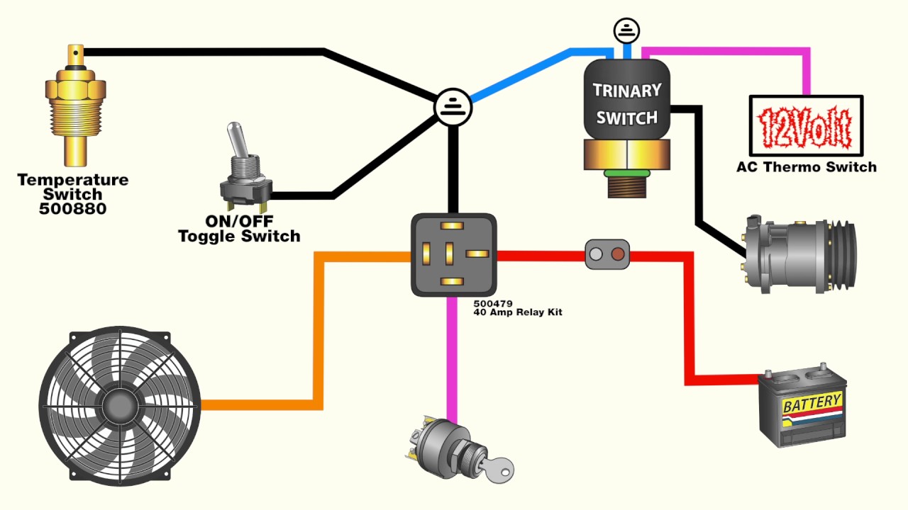
* **Electric Radiator Fan:** The fan itself, typically rated for a specific voltage (usually 12V DC) and current draw. The ampere (A) rating is very important. * **Temperature Sensor (or Thermostat):** A device that monitors the engine coolant temperature and provides a signal when a specific temperature threshold is reached. * **Relay:** An electromagnetic switch that allows a low-current signal from the temperature sensor to control a high-current circuit powering the fan motor. This prevents damage to the temperature sensor and wiring. * **Fuse:** A safety device that protects the wiring and fan motor from overcurrent. * **Wiring and Connectors:** High-quality automotive-grade wiring and connectors are essential for a reliable and safe installation.Wiring Diagram and Steps:
Here's a general wiring diagram and step-by-step guide:
- Ground Connection: Connect the fan motor's ground wire (typically black) to a clean, reliable ground point on the vehicle's chassis. Ensure the connection is free of paint or rust for optimal conductivity. A star washer can help ensure a solid connection.
- Power Connection (Relay): The positive wire (typically red) from the fan motor connects to terminal 87 on the relay.
- Relay Power Source: Connect a wire from the vehicle's battery positive terminal (with an appropriately sized fuse – see sizing information below) to terminal 30 on the relay. This provides the high-current power for the fan.
- Relay Control (Temperature Sensor): Connect one wire from the temperature sensor to terminal 86 on the relay. This triggers the relay.
- Relay Ground (or Switched Power): There are two common methods for the terminal 85 connection:
- Ground Method: Connect terminal 85 to a chassis ground. The temperature sensor then *completes* the circuit to ground when the target temperature is reached, activating the relay. This method uses a temperature sensor that switches to ground.
- Switched Power Method: Connect terminal 85 to a 12V switched power source (e.g., ignition-switched power). The temperature sensor then *interrupts* the power circuit when the target temperature is reached, deactivating the relay. This method uses a temperature sensor that breaks the circuit on temperature threshold. Be very careful to determine which type of sensor you have before wiring!
- Fuse Installation: Install an appropriately sized fuse in the wire connecting the battery positive terminal to relay terminal 30. Fuses are crucial for safety.
Fuse Sizing: The fuse size should be slightly larger than the fan's rated current draw but smaller than the wiring's current carrying capacity. Consult the fan's specifications for its ampere (A) rating. A good rule of thumb is to use a fuse that's 125% of the fan's continuous current draw. For example, if the fan draws 10 amps, use a 12.5 amp fuse (round up to the nearest available size, like 15 amps). The wire gauge should also be appropriately sized for the current draw. Consult a wire gauge chart to ensure adequate current carrying capacity.
Temperature Sensor Placement: The temperature sensor should be placed in a location where it accurately reflects the engine's coolant temperature. Common locations include the radiator (for a radiator-mounted sensor) or the engine block (for a threaded sensor). Adapters may be required to fit the sensor into existing coolant passages. An inline adapter in the upper radiator hose is also a popular choice.
Fan Controller Units
For more sophisticated control, consider using a dedicated fan controller unit. These units often provide features such as:
* Adjustable Temperature Settings: Allows you to fine-tune the temperature at which the fan activates. * PWM (Pulse Width Modulation) Control: Allows variable fan speed control, providing smoother operation and reduced noise. * Soft Start: Gradually increases fan speed to reduce the initial current surge. * Override Switch: Allows you to manually activate the fan, regardless of temperature.Wiring a fan controller involves connecting the controller to the fan, temperature sensor, and power source according to the manufacturer's instructions. These controllers offer a more refined and reliable solution compared to basic relay-based circuits.
Common Issues and Maintenance Concerns
* Overheating: If the fan isn't activating or is not powerful enough, the engine may overheat. Check the wiring, fuse, relay, and temperature sensor. Verify that the fan is properly sized for the application. * Fuse Blows: A blown fuse indicates an overcurrent condition. Check the wiring for shorts or damage. The fan motor itself may be drawing excessive current due to wear or damage. * Relay Failure: Relays can fail over time due to repeated switching. Replace the relay if it is suspected of being faulty. * Wiring Corrosion: Corrosion can cause poor connections and voltage drops. Inspect and clean all wiring connections regularly. Apply dielectric grease to connectors to prevent corrosion. * Temperature Sensor Malfunction: A faulty temperature sensor can prevent the fan from activating or cause it to run continuously. Test the sensor's resistance at different temperatures to verify its accuracy. * Fan Motor Failure: The fan motor itself can fail due to wear or damage. Replace the fan if the motor is not functioning correctly.Do's and Don'ts / Best Practices
* DO use high-quality automotive-grade wiring and connectors. * DO use a relay to protect the temperature sensor and wiring. * DO use an appropriately sized fuse to protect the wiring and fan motor. * DO ensure all wiring connections are clean and secure. * DO use dielectric grease on connectors to prevent corrosion. * DO properly size the fan for your application. * DO consult the manufacturer's instructions for the fan, temperature sensor, and any other components. * DON'T use household wiring or connectors. * DON'T overload the circuit with too much current. * DON'T skip the fuse. It's a crucial safety device. * DON'T run the wiring near sharp edges or hot components without protection. * DON'T assume the fan is working correctly without proper testing. * DON'T overtighten connectors, which can damage them.Conclusion
Wiring an electric radiator fan is a relatively straightforward project that can offer significant benefits in terms of fuel economy, engine performance, and temperature control. By following the steps outlined in this article and adhering to best practices, you can ensure a successful and reliable installation. Always prioritize safety and double-check your work before operating the vehicle. Consider using a fan controller unit for more advanced features and enhanced reliability. Choosing high-quality components and paying attention to detail will result in a long-lasting and effective cooling system upgrade. Always consult a qualified mechanic if you are unsure about any aspect of the installation process.