In World War I What Was The R34
Alright, let's dive into the R34, not the Skyline this time, but the British airship R34. Think of this as understanding the inner workings of a complex, albeit outdated, flying machine. Just like understanding your car's engine helps with repairs and modifications, understanding the R34's mechanics allows us to appreciate the ingenuity and challenges of early aviation engineering. While you won't be overhauling one in your garage (probably!), the principles of lift, propulsion, and control are universal and can enhance your understanding of other mechanical systems. We have the original diagrams and schematics for this magnificent machine, and you can download them at the end of this article.
Key Specs and Main Parts of the R34
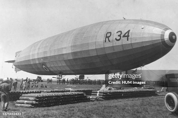
The R34 was a non-rigid airship, meaning it maintained its shape through internal gas pressure rather than a rigid internal framework like Zeppelins. Here are some key specifications:
- Length: 643 feet (196 meters)
- Diameter: 79 feet (24 meters)
- Gas Capacity: 1,950,000 cubic feet (55,200 cubic meters) of hydrogen (H2)
- Engines: Five Sunbeam Maori IV 275 hp engines
- Maximum Speed: 62 mph (100 km/h)
- Range: Approximately 3,400 nautical miles
- Crew: Roughly 30 officers and men
The main parts of the R34 can be broken down into several systems:
Envelope and Gas Bags
This is the main body of the airship, the large fabric bag containing the lighter-than-air gas. Instead of one massive compartment, the R34 utilized 19 separate gas bags, each containing hydrogen. This compartmentalization was a critical safety feature; a single puncture wouldn't lead to catastrophic gas loss. Think of it like having multiple fuel cells in a modern vehicle – redundancy is key. The envelope itself was made of multiple layers of fabric, often cotton coated with a gas-impermeable dope.
Control Car and Gondolas
The control car, suspended beneath the envelope, housed the flight controls, navigation equipment, and crew quarters. Imagine the cockpit of an aircraft, but much larger and connected to the rest of the ship by a narrow walkway. The gondolas, also suspended below, housed the engines and sometimes additional crew. Each gondola contained an engine, a propeller, fuel tanks, and the necessary controls for engine operation. Maintaining precise engine synchronization across all five engines was a major challenge for the engineers.
Engines and Propulsion
The R34 was powered by five Sunbeam Maori IV inline 12-cylinder engines. These engines were relatively powerful for their time, producing 275 horsepower each. The engines drove large two-bladed wooden propellers. Just like with car engines, regular maintenance and precise adjustments were crucial for reliable operation. Overheating, vibration, and fuel delivery problems were common issues.
Control Surfaces
The R34 utilized rudders for yaw (horizontal direction), elevators for pitch (vertical direction), and a system of ballonets for controlling trim (the airship's balance). Rudders and elevators were fabric-covered surfaces located at the tail of the airship, similar to an airplane. Ballonets were internal air bags within the envelope that could be inflated or deflated to compensate for changes in gas pressure and temperature, affecting lift and buoyancy.
Symbols and Diagram Interpretation
Understanding the diagrams requires grasping some basic conventions. Lines represent structural components, gas lines, control cables, and electrical wiring. Different line weights often indicate the thickness or importance of a component. For example:
- Solid lines: Main structural members or high-pressure lines.
- Dashed lines: Secondary components or low-pressure lines.
- Dotted lines: Control cables or lines hidden from view.
Colors, if present (some older diagrams are only black and white), can denote different fluids or gases. For instance, red might indicate fuel, blue might represent water for engine cooling, and green might signify compressed air.
Icons represent various components such as valves, pumps, instruments, and engine parts. A circle with an "X" inside might represent a valve, while a square with a wavy line inside might depict a fuel tank. The legend on the diagram will provide a key to all the symbols used.
How It Works
The R34 worked on the principle of buoyancy. The hydrogen gas, being lighter than air, provided lift. The engines provided thrust for forward motion, and the control surfaces allowed for steering and altitude control. The ballonets played a crucial role in maintaining the airship's shape and stability. As the airship ascended or descended, the gas within the envelope expanded or contracted due to changes in atmospheric pressure. The ballonets were inflated or deflated with air to compensate for these volume changes, preventing the envelope from becoming too slack or over-pressurized.
Steering was accomplished using the rudders and elevators, controlled by cables running from the control car to the tail. The pilot could adjust the rudder to turn the airship left or right, and the elevators to climb or descend.
Real-World Use and Basic Troubleshooting
While you won't be fixing an R34 anytime soon, understanding its systems can inform your approach to troubleshooting other mechanical problems.
- Engine Problems: Just like a car engine, the R34's engines were prone to issues. Common problems included overheating, misfires, and fuel delivery problems. Troubleshooting involved checking the spark plugs, fuel lines, and cooling system.
- Gas Leaks: Hydrogen leaks were a constant concern. Regular inspections were crucial to identify and repair any leaks. Using soapy water around seams and fittings was a common method for detecting leaks.
- Control Cable Issues: Snapped or frayed control cables could render the airship uncontrollable. Regular inspection and lubrication of the cables were essential.
- Ballonet Problems: Leaks or failures in the ballonet system could affect the airship's stability and control. These systems required careful monitoring and maintenance.
If the airship was losing altitude rapidly despite the elevators being set for level flight, the crew would investigate for gas leaks. If the engines were running unevenly, they'd check the spark plugs and fuel mixture settings.
Safety - Risky Components
The most significant safety hazard was, of course, the hydrogen gas. Hydrogen is extremely flammable, and even a small spark could ignite it, leading to a catastrophic explosion. Smoking was strictly prohibited on board, and all electrical equipment had to be carefully shielded to prevent sparks. Static electricity was also a major concern.
The engines themselves posed a risk. Engine fires were a possibility, and the propellers were extremely dangerous. Proper engine maintenance and adherence to safety protocols were paramount.
Finally, the sheer size of the airship made it vulnerable to strong winds. Landing and maneuvering in gusty conditions required extreme skill and caution. The envelope, though robust, was susceptible to tears and punctures, especially during handling on the ground.
By carefully managing these risks, the R34 made its historic transatlantic flight, demonstrating the potential of airship technology. While airships are largely obsolete today, their legacy lives on in the principles of aerodynamics, propulsion, and control that are still relevant to modern aviation and engineering. This is a complex piece of machinery, by understanding this engineering marvel, you can better understand more modern machines.
Now that you have a better understanding of the R34, you can download the original diagrams to study it in more detail. This will allow you to explore the schematics of this amazing invention.