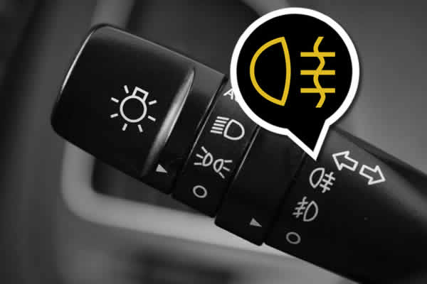
Symbol How To Turn On Fog Lights
This article provides a detailed technical explanation of how to activate fog lights in a typical automotive electrical system. We will explore the wiring diagram, component functions, and troubleshooting techniques necessary for understanding and maintaining your vehicle's fog light system. Whether you're performing repairs, upgrading your fog lights, or simply expanding your automotive knowledge, this information will be invaluable.
Key Specs and Main Parts
A fog light system, at its core, consists of the following primary components:
- Fog Lights (Lamps): These are specifically designed to provide a wide, low beam of light, reducing glare in foggy conditions. They typically use halogen, LED, or HID bulbs.
- Relay: An electrically operated switch that allows a low-current circuit (the switch in the cabin) to control a high-current circuit (powering the fog lights). This is a crucial safety and circuit protection measure.
- Switch: Located inside the vehicle, this controls the fog lights. Often integrated with other lighting controls.
- Fuse: A safety device that protects the circuit from overcurrent. If the current exceeds the fuse's rating, it blows, interrupting the circuit.
- Wiring Harness: A bundle of wires connecting the components, ensuring power and signals reach their destinations. Wire gauge (thickness) is important to handle the current.
- Ground Connection(s): Provides a return path for current, completing the electrical circuit. Clean, secure grounds are essential for reliable operation.
Typical specifications you might encounter include:
- Voltage: Usually 12V DC in automotive applications.
- Bulb Wattage: Varies depending on the type of bulb and the fog light design (e.g., 55W halogen, 10-20W LED).
- Fuse Rating: Specified in Amperes (A), chosen based on the total current draw of the fog lights plus a safety margin. A common value is 10A or 15A.
- Relay Rating: The relay must be rated to handle the current drawn by the fog lights. Look for a relay with a contact rating that exceeds the fog lights' combined amperage draw.
- Wire Gauge: The wire thickness (gauge) is selected to carry the current without excessive voltage drop or overheating. Consult a wiring chart based on the length of the wire and the expected current.
Symbols and Wiring Diagram Explanation
Understanding the symbols in a wiring diagram is fundamental to tracing the circuit and troubleshooting effectively. Here are some common symbols you'll encounter:
- Straight Line: Represents a wire. The thickness of the line *doesn't* necessarily correlate to wire gauge.
- Dotted Line: Often indicates a wire that is part of a larger harness, or a connection that might be optional depending on the vehicle configuration.
- Ground Symbol (usually three horizontal lines decreasing in size): Indicates a connection to the vehicle chassis, providing a return path for current. Grounds are critical for proper operation.
- Battery Symbol (+ and -): Represents the vehicle's battery, the source of electrical power.
- Fuse Symbol (zigzag line inside a rectangle): Represents a fuse, a circuit protection device.
- Switch Symbol (a line bridging or not bridging two terminals): Represents a switch, which opens or closes the circuit.
- Relay Symbol (coil and a switch): The coil, when energized, closes the switch, connecting the high-current circuit.
- Lamp Symbol (circle with an "X" inside): Represents the fog light bulb.
Colors: Wire colors are typically indicated using abbreviations (e.g., BLK for black, RED for red, BLU for blue, GRN for green, YEL for yellow, WHT for white). Combinations are common (e.g., BLU/WHT for blue with a white stripe). Using a multimeter, you can also check if that wire leads to Ground, Source, or Load.
Reading a Wiring Diagram: Start at the power source (battery), trace the circuit through the fuse, switch, relay coil, relay contacts, fog lights, and finally back to ground. Pay attention to wire colors and connections. The diagram shows the *electrical* connections, not necessarily the *physical* locations of components in the vehicle.
How It Works
The fog light system operates as follows:
- The driver activates the fog light switch inside the vehicle.
- This switch completes a low-current circuit that energizes the relay coil.
- When the relay coil is energized, it creates a magnetic field that pulls the relay contacts closed.
- Closing the relay contacts completes the high-current circuit between the battery, the fuse, and the fog lights.
- The fog lights illuminate, providing enhanced visibility in foggy conditions.
The relay is crucial because it allows the switch to be small and carry only a small amount of current. The fog lights themselves draw significant power, and routing that high current through a small switch would be unsafe and could damage the switch.
Real-World Use – Basic Troubleshooting Tips
Here are some common fog light problems and troubleshooting steps:
- Fog lights don't turn on at all:
- Check the fuse. A blown fuse is the most common cause.
- Check the bulb(s). Replace any burned-out bulbs.
- Check the relay. You can test the relay by swapping it with a known-good relay or using a multimeter to test for continuity.
- Check the switch. Use a multimeter to verify that the switch is providing power to the relay coil when activated.
- Check the ground connections. Ensure they are clean and secure. A poor ground can cause intermittent or complete failure.
- Check wiring harness. Look for cut wires, damaged connectors, and corrosion. Use a multimeter to check for voltage and continuity along the circuit.
- Fog lights flicker or turn on intermittently:
- Check the ground connections. This is often the culprit.
- Check the wiring harness for loose connections or damaged wires.
- Inspect the relay for signs of corrosion or damage.
- Fog lights are dim:
- Check the ground connections. A poor ground can reduce voltage to the lights.
- Check the battery voltage. A low battery can cause dim lights.
- Inspect the wiring for corrosion or damage, which can increase resistance and reduce voltage.
Safety – Highlight Risky Components
Working with automotive electrical systems can be hazardous. Here are some key safety precautions:
- Disconnect the battery: Always disconnect the negative battery terminal before working on any electrical components. This prevents accidental shorts and potential electrical shock.
- Be careful with wiring: Avoid cutting or damaging wires. Use proper wiring tools and techniques. When splicing wires, use properly crimped connectors and protect them with heat shrink tubing.
- Fuse Placement: When replacing a fuse, always use a fuse with the correct amperage rating. Using a higher-rated fuse can overload the circuit and cause a fire.
- Relay Caution: Relay failure can sometimes cause damage to other components if not addressed promptly. Replace suspect relays immediately.
- Avoid Water: Never work on electrical systems in wet conditions.
- High-Intensity Discharge (HID) Bulbs: HID bulbs operate at very high voltage and can be dangerous if handled improperly. If you are working with HID fog lights, consult the manufacturer's instructions and take extra precautions to avoid electrical shock. *It is recommended to let a professional handle any HID work.*
- Proper Tools: Make sure to have the right tools for the job, including wire strippers, crimpers, multimeters, and test lights.
This article provides a general overview of fog light systems. Specific wiring diagrams and component locations vary from vehicle to vehicle. Always consult your vehicle's service manual for detailed information specific to your make and model. It is highly recommended to compare this general information with the manual to gain a better understanding of your specific fog light system.
We have a simplified sample wiring diagram available for download, showing the basic components and connections described in this article. This diagram can serve as a helpful visual aid while you're learning about fog light systems.
Remember to always prioritize safety and consult with a qualified mechanic if you are unsure about any aspect of electrical repair.