What Are High Beams And Low Beams
Understanding your vehicle's lighting system is crucial, whether you're diagnosing a faulty bulb, upgrading to LEDs, or simply want to be a more informed driver. This article focuses on high beams and low beams, the cornerstones of nighttime visibility. We'll delve into their purpose, construction, operation, and troubleshooting, providing you with the knowledge to confidently tackle related issues. Having a solid understanding of these systems is invaluable for safe driving and efficient vehicle maintenance. And to aid you further, we have a detailed wiring diagram file available for download.
Key Specs and Main Parts
Both high beams (also known as main beams) and low beams utilize similar fundamental components, but their configuration and light output differ significantly. Here's a breakdown:
Main Parts:
- Bulb/Light Source: This is the heart of the system. Older vehicles typically use halogen bulbs (specifically H7 or H4 types for headlights that combine high and low beams in a single bulb). Newer vehicles increasingly employ LEDs (Light Emitting Diodes) or, less commonly, HID (High-Intensity Discharge) lamps. LEDs offer greater efficiency and lifespan, while HIDs provide very bright light but require ballasts.
- Reflector: The reflector is a precisely shaped, mirrored surface behind the bulb. Its purpose is to collect the light emitted by the bulb and redirect it in a focused beam forward. The reflector's geometry is critical for the beam pattern – different shapes create different patterns. High beam reflectors tend to be deeper and wider to maximize light output and project it over a longer distance.
- Lens: The lens, located in front of the bulb and reflector, further shapes and directs the light beam. Modern headlights often incorporate a projector lens, which uses a lens to focus the light before it exits the headlight assembly, providing a sharper cutoff and more controlled beam pattern. Low beams almost always use projector lenses to prevent glare.
- Wiring Harness: The wiring harness connects the headlight assembly to the vehicle's electrical system, supplying power to the bulb and controlling the switching between high and low beams. Expect to see different gauge wires for power and ground, and potentially additional wires for features like daytime running lights (DRLs) or turn signals.
- Switch/Relay: The headlight switch (typically on the steering column or dashboard) activates the headlights. A relay is often used to handle the high current draw of the headlights. The relay acts as an intermediary switch, allowing a small current from the headlight switch to control a larger current to the headlights.
Key Specs:
- Voltage: Headlights operate on the vehicle's standard electrical system voltage, typically 12V DC.
- Wattage: The wattage of the bulb determines its light output. Common halogen headlight wattages range from 55W to 65W. LED replacements should have comparable or slightly lower wattage (while providing higher light output due to greater efficiency).
- Lumen Output: Measured in lumens, this indicates the total amount of light emitted. Higher lumens generally mean brighter light.
- Color Temperature: Measured in Kelvin (K), this describes the color of the light. Halogen bulbs typically have a color temperature around 3000K (warm white), while LEDs often range from 5000K to 6500K (cool white to daylight).
Symbols
Understanding the symbols in a headlight wiring diagram is essential for troubleshooting and repairs. Here are some common symbols you'll encounter:
- Solid Lines: Indicate electrical wires. Thicker lines usually represent wires carrying higher current.
- Dashed Lines: May represent shielded wires, ground connections, or signal wires.
- Circles: Often represent electrical components like bulbs, switches, or relays.
- Resistors: Represented by a zigzag line.
- Ground Symbol: Usually looks like a series of horizontal lines decreasing in length, indicating a connection to the vehicle's chassis ground.
- Headlight Switch Symbol: A switch symbol with lines indicating the different positions (off, parking lights, low beams, high beams).
- Relay Symbol: Shows a coil and a switch. The coil, when energized, closes or opens the switch contacts.
Color Coding: Wiring diagrams commonly use color-coded wires. While the specific colors may vary between manufacturers and models, some common conventions include:
- Red: Often used for positive (+) power supply.
- Black: Typically used for ground (-).
- Yellow or White: May be used for low beam power.
- Blue or Green: May be used for high beam power.
Always refer to the specific wiring diagram for your vehicle model to confirm the color codes.
How It Works
The fundamental principle is simple: the headlight switch completes a circuit, allowing power to flow to the headlight bulbs. However, the switching mechanism for high and low beams involves a more complex circuit. Here's a simplified explanation:
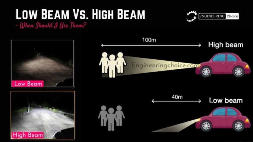
- Low Beams: When the headlight switch is set to the low beam position, power flows through the wiring harness to the low beam filament (or LED element) in the headlight bulb. The reflector and lens are designed to direct the light downwards and to the sides, illuminating the road ahead without blinding oncoming traffic. Projector lenses are crucial for creating a sharp horizontal cutoff, preventing glare.
- High Beams: When the high beams are activated (often by pushing or pulling the headlight stalk), a separate circuit is energized. This either activates the high beam filament in the bulb (if using a dual-filament bulb like an H4) or activates a separate high beam bulb or LED element. High beams are designed to project light further down the road and with a wider beam angle, providing maximum visibility in dark conditions. The reflector in a high beam assembly is shaped to maximize distance.
- Relay Operation: The headlight switch typically controls a relay. When the switch is activated, it energizes the relay coil, which then closes the relay contacts, allowing a high current to flow directly from the battery to the headlights. This protects the headlight switch from damage due to the high current draw of the headlights.
Real-World Use – Basic Troubleshooting Tips
Here are some common issues and troubleshooting steps:
- Headlights Not Working: Check the fuse. A blown fuse is the most common cause. If the fuse blows repeatedly, there's a short circuit somewhere in the system. Inspect the wiring for damage or exposed wires.
- One Headlight Not Working: Replace the bulb. If the new bulb doesn't work, check the wiring harness for corrosion or loose connections. Use a multimeter to check for voltage at the bulb socket. If there's no voltage, trace the wiring back to the fuse box and headlight switch.
- High Beams Don't Work: Check the high beam fuse. If the low beams work but the high beams don't, the problem is likely in the high beam circuit. Test the high beam switch and relay.
- Dim Headlights: This can be caused by corroded connections, a weak ground, or a failing alternator. Clean all connections in the headlight circuit and check the battery voltage.
- Flickering Headlights: Often caused by a loose connection or a failing relay. Check all connections and replace the relay if necessary.
Safety
Working with electrical systems carries risks. Always disconnect the negative battery terminal before working on any electrical components.
Warning: HID headlights use high voltage. Never touch the HID ballast or bulb connectors while the system is energized. Allow the system to fully discharge before handling HID components.
When testing circuits, use a multimeter and follow proper safety procedures. Always wear eye protection when working under the hood of a vehicle.
Furthermore, when replacing bulbs, avoid touching the glass portion of halogen bulbs with your bare hands. The oils from your skin can create hot spots that shorten the bulb's lifespan. Use gloves or a clean cloth when handling halogen bulbs.
This overview should provide a strong foundation for understanding high and low beam systems. For even greater detail and troubleshooting assistance, download the comprehensive wiring diagram file we've prepared. It provides a visual representation of the circuit layout, component locations, and wiring connections, allowing for confident diagnosis and repair of lighting issues.