What Causes Abs Light To Come On
The dreaded ABS light. Seeing it illuminate on your dashboard can be alarming, but understanding the system and potential causes empowers you to diagnose and possibly even fix the problem yourself. This article dives deep into the Anti-lock Braking System (ABS), explaining its components, how it functions, and common reasons why the ABS light might activate. Consider this your go-to guide for troubleshooting your ABS, potentially saving you a trip to the mechanic. We also have a detailed ABS system diagram available for download, further aiding your understanding and repair efforts.
Why This Matters: Understanding Your ABS
Understanding your ABS is critical for both safety and cost savings. A malfunctioning ABS can significantly impair your braking performance, especially in emergency situations. By understanding the system, you can accurately diagnose issues, potentially perform repairs yourself (saving on labor costs), and ensure your vehicle's braking system functions as designed. This knowledge also helps you communicate more effectively with mechanics, ensuring you get the correct repairs done without unnecessary expenses.
Key Specs and Main Parts
The ABS system is composed of several key components working in unison. Let's break them down:
- Wheel Speed Sensors (WSS): Located at each wheel, these sensors monitor the rotational speed of the wheels. They are typically either variable reluctance sensors or Hall-effect sensors. Variable reluctance sensors generate an AC voltage signal proportional to wheel speed, while Hall-effect sensors use a magnetic field to create a digital signal.
- ABS Control Module (ECU/PCM): The "brain" of the ABS, it receives signals from the wheel speed sensors and determines if a wheel is locking up during braking. Based on this information, it controls the hydraulic modulator. This may be part of the Powertrain Control Module (PCM).
- Hydraulic Modulator (HCU): This unit contains valves and a pump to control brake pressure to each wheel independently. The valves can increase, decrease, or hold pressure based on signals from the control module. It allows for the modulation of brake fluid pressure.
- Brake Booster and Master Cylinder: These are fundamental components of the braking system itself and supply the initial hydraulic pressure. While not exclusive to the ABS, their proper functioning is critical for the ABS to operate correctly.
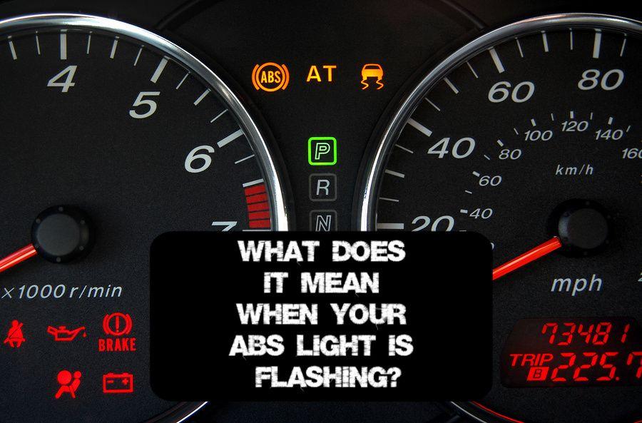
- ABS Warning Light: This light on your dashboard indicates a fault within the ABS system. Note that some vehicles may also have a separate Brake warning light that indicates a problem with the base braking system (low fluid, parking brake engaged, etc.).
Decoding the Diagram: Symbols and Lines
The ABS system diagram uses standardized symbols to represent the various components and connections. Here's a breakdown of common symbols:
- Solid Lines: Represent electrical wiring. Different colors typically indicate different circuits or functions (e.g., power, ground, signal).
- Dashed Lines: Often represent hydraulic lines carrying brake fluid.
- Rectangles: Commonly used to represent electronic components like the control module, relays, and sensors.
- Circles: May represent mechanical components like the hydraulic modulator pump or individual wheel speed sensors.
- Ground Symbol: A series of horizontal lines diminishing in size, indicating a connection to the vehicle's chassis ground.
- Connector Symbols: Depict connections between wires or components.
Understanding these symbols is crucial for tracing circuits, identifying components, and troubleshooting electrical problems within the ABS.
How It Works: Preventing Wheel Lockup
The ABS works by preventing wheels from locking up during braking. Here's a step-by-step explanation:
- Wheel Speed Monitoring: The wheel speed sensors continuously monitor the rotational speed of each wheel and send this data to the ABS control module.
- Lockup Detection: If the control module detects that a wheel is decelerating rapidly (indicating imminent lockup), it activates the hydraulic modulator.
- Pressure Modulation: The hydraulic modulator adjusts the brake pressure to that specific wheel. It can do this in three phases:
- Pressure Reduction: Reduces brake pressure to prevent the wheel from locking up.
- Pressure Holding: Holds the pressure constant if the wheel is approaching lockup.
- Pressure Increase: Gradually increases the pressure again to resume braking force, as long as lockup is not imminent.
- Cycle Repetition: This cycle of pressure modulation happens rapidly and repeatedly (several times per second) to maintain optimal braking performance without wheel lockup.
- Driver Feedback: During ABS activation, the driver may feel a pulsating sensation in the brake pedal. This is normal and indicates that the system is actively preventing wheel lockup.
By preventing wheel lockup, the ABS allows the driver to maintain steering control and reduce stopping distances, especially on slippery surfaces.
Real-World Use: Basic Troubleshooting
When the ABS light comes on, it indicates a problem within the system. Here are some basic troubleshooting steps you can take:
- Check Brake Fluid Level: Low brake fluid can sometimes trigger the ABS light. Top it off to the recommended level and check for leaks.
- Inspect Wheel Speed Sensors: Visually inspect the wheel speed sensors and their wiring for damage, corrosion, or loose connections. Clean the sensors if they are dirty. A broken or corroded WSS is one of the most common ABS issues.
- Check ABS Fuses and Relays: Locate the ABS fuses and relays in your vehicle's fuse box and check if any are blown or faulty. Replace them if necessary.
- Scan for Diagnostic Trouble Codes (DTCs): Use an OBD-II scanner to retrieve any DTCs stored in the ABS control module. These codes can provide valuable clues about the nature of the problem. Common codes relate to wheel speed sensor failures, valve malfunctions in the hydraulic modulator, or communication errors within the system. Note: A basic OBD-II scanner may not be able to read ABS codes; you may need a scanner specifically designed for ABS diagnostics.
- Test Wheel Speed Sensors: If you have a multimeter, you can test the wheel speed sensors for proper resistance and voltage output. Consult your vehicle's service manual for specific testing procedures and values.
If these basic troubleshooting steps don't resolve the issue, it's best to consult a qualified mechanic for further diagnosis and repair.
Safety: Proceed with Caution
Working on the braking system can be dangerous if not done correctly. Here are some safety precautions to keep in mind:
- Brake Fluid: Brake fluid is corrosive and can damage painted surfaces. Wipe up any spills immediately.
- Electrical Components: Disconnect the battery before working on any electrical components of the ABS to prevent accidental short circuits.
- Hydraulic Pressure: Be aware that the brake system contains pressurized fluid. Depressurize the system before disconnecting any brake lines. Refer to your vehicle's service manual for the proper procedure.
- Proper Tools: Use the correct tools for the job to avoid damaging components.
- Brake Bleeding: After working on the hydraulic system, you will need to bleed the brakes to remove any air bubbles. This is a critical step to ensure proper braking performance.
- Always Test Drive: After performing any repairs, test drive the vehicle in a safe area to ensure the brakes are functioning correctly. Perform several stops at different speeds to verify ABS activation.
The hydraulic modulator contains high-pressure brake fluid and complex valve systems. Do not attempt to disassemble or repair the hydraulic modulator yourself unless you have specialized training and equipment.
Your ABS Diagram Awaits
We've covered the basics of the ABS system and potential causes for the warning light. To further aid your troubleshooting and repair efforts, we have a detailed ABS system diagram available for download. This diagram will provide a visual representation of the system's components and their connections, making it easier to identify and diagnose problems. It’s an invaluable resource for any DIY mechanic tackling ABS issues.
Download the ABS system diagram and take your understanding to the next level! Remember, safety is paramount, and when in doubt, consult a qualified mechanic.