What Do All The Car Lights Mean
Understanding your car's lighting system goes beyond simply knowing where the headlight switch is. It's about comprehending a complex network of circuits, sensors, and bulbs, all working in concert to ensure your safety and visibility on the road. This guide is designed for the intermediate car owner, modder, or DIY mechanic looking to delve deeper into the intricacies of automotive lighting. This information is crucial for troubleshooting electrical issues, performing modifications, and gaining a thorough understanding of your vehicle.
Purpose: Why Lighting Diagrams Matter
Why should you care about understanding car lighting diagrams? Several reasons. First, troubleshooting. When a light fails, knowing the circuit allows you to pinpoint the fault – is it the bulb, the switch, a relay, or a wiring issue? Second, modifications. Planning to add auxiliary lights, upgrade your headlights to LEDs, or install a custom lighting system? A diagram is essential to ensure proper wiring and avoid overloading circuits. Third, repairs. Replacing a damaged wiring harness or faulty control module becomes much easier with a clear understanding of the lighting system's layout. Finally, simply knowledge and empowerment. Understanding your car's systems enhances your ability to maintain and improve your vehicle.
Key Specs and Main Parts
A typical automotive lighting system consists of several key components:
- Battery: The primary power source for all electrical components, including the lights.
- Fuses: Protective devices that break the circuit if an overcurrent occurs, preventing damage to components and wiring. Each light circuit will typically have its own fuse.
- Relays: Electrically operated switches that control high-current circuits using a low-current signal. Headlights, in particular, often use relays.
- Switches: Used to manually control the various lights, such as headlights, taillights, turn signals, and interior lights.
- Wiring Harness: A collection of wires bundled together and routed throughout the vehicle, connecting the various components of the lighting system.
- Control Modules (BCM, ECM): Modern vehicles often use Body Control Modules (BCMs) or Engine Control Modules (ECMs) to manage lighting functions, including automatic headlights, daytime running lights (DRLs), and advanced lighting features.
- Light Bulbs/LEDs: The actual light-emitting devices, available in various types (halogen, incandescent, LED, HID/Xenon).
- Sensors: Some lighting systems utilize sensors (e.g., ambient light sensors) to automatically adjust light output or activate lights under certain conditions.
Key specifications to consider include voltage (typically 12V in passenger vehicles), wattage (power consumption of the bulbs), and amperage (current draw of the circuits). Understanding these specs is crucial when replacing bulbs or adding aftermarket lighting.
Symbols: Deciphering the Diagram
Automotive wiring diagrams use a standardized set of symbols to represent various components. Learning these symbols is key to understanding the diagram. Here's a breakdown of some common symbols:
- Solid Lines: Represent wires. Thicker lines generally indicate higher current-carrying capacity.
- Dashed Lines: Often represent wires or circuits that are optional, not always present, or part of a control system.
- Ground Symbol (usually three horizontal lines diminishing in size): Indicates a connection to the vehicle's chassis, providing a return path for the current.
- Bulb Symbol (circle with an 'X' inside): Represents a light bulb.
- Switch Symbol (line with a break): Indicates a switch. The type of switch (e.g., SPST, SPDT, DPDT) is indicated by the number of poles and throws in the symbol.
- Relay Symbol (coil and a switch): Shows the relay coil and the switch it controls.
- Fuse Symbol (zigzag line inside a rectangle): Represents a fuse. The fuse rating (in amps) is usually indicated near the symbol.
- Connector Symbol (two interlocking shapes): Shows a connector where wires can be disconnected.
- Resistor Symbol (zigzag line): Represents a resistor.
- Diode Symbol (triangle pointing to a line): Represents a diode, which allows current to flow in only one direction.
- Capacitor Symbol (two parallel lines): Represents a capacitor, which stores electrical energy.
Colors are also crucial. Wires are color-coded to aid in identification. While color codes vary between manufacturers and even between models, there are some common conventions. For example, black is almost always ground, and red is often a positive power wire. Always refer to the specific wiring diagram for your vehicle to verify the color codes.
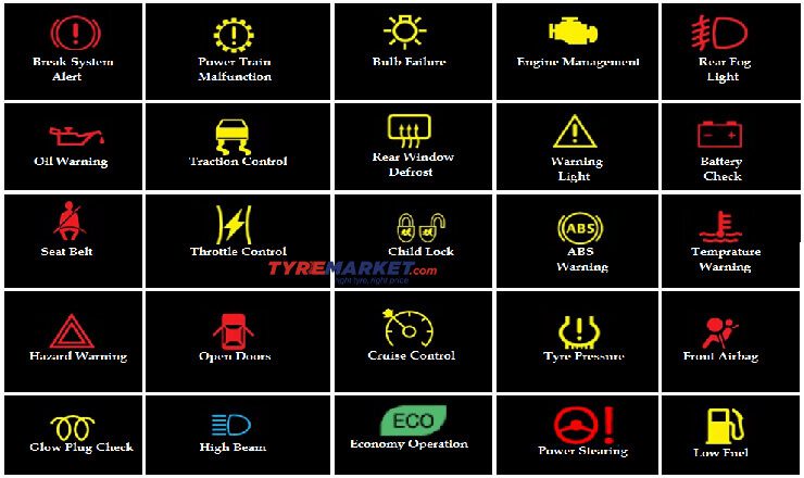
Icons often represent specific lighting functions. For example, a headlight icon indicates the headlight circuit, a taillight icon indicates the taillight circuit, and so on.
How It Works: A Simplified Explanation
The basic principle is simple: electricity flows from the battery, through a switch (controlled by the driver), to the light bulb, and then back to the battery through the ground. However, modern lighting systems are more complex. Here's a more detailed explanation:
- Power Source: The battery provides the initial electrical energy.
- Circuit Protection: A fuse protects the circuit from overcurrent.
- Switch Control: The driver activates the switch, completing the circuit. In some cases, the switch signals a control module (BCM/ECM).
- Relay Activation (if applicable): The switch activates a relay, which then closes the high-current circuit to the lights. This is common for headlights, as they draw a significant amount of current.
- Power Distribution: The power flows through the wiring harness to the light bulb.
- Light Emission: The bulb converts electrical energy into light.
- Ground Return: The electricity returns to the battery through the vehicle's chassis ground.
Modern vehicles often use control modules (BCMs) to manage lighting functions. These modules receive signals from various sensors and switches and control the lights accordingly. For example, the BCM might activate the headlights automatically when the ambient light sensor detects low light conditions.
It's important to understand that some circuits may be 'always hot,' meaning they are powered directly from the battery and are not controlled by the ignition switch. Others are only powered when the ignition is turned on.
Real-World Use: Basic Troubleshooting Tips
Here are some basic troubleshooting tips for common lighting problems:
- Light Doesn't Work: First, check the bulb. If the bulb is good, check the fuse. If the fuse is blown, replace it with a fuse of the same amperage. If the fuse blows again immediately, there's likely a short circuit in the wiring.
- Headlights Dim: Check the battery voltage. A low battery can cause dim headlights. Also, check the headlight grounds for corrosion or loose connections.
- Turn Signal Blinks Too Fast: This usually indicates a burnt-out turn signal bulb. Replace the bulb and check the wiring.
- Tailights Not Working: Check the bulbs, fuses, and wiring. Also, check the brake light switch, as it often controls the taillights.
When troubleshooting, always use a multimeter to check for voltage and continuity. A multimeter is an invaluable tool for diagnosing electrical problems.
Safety: Risky Components
Working with automotive electrical systems can be dangerous if you're not careful. Always disconnect the negative battery terminal before working on any electrical components. This will prevent accidental short circuits and electrical shocks.
Be aware of airbags. Some wiring harnesses run near airbag sensors and modules. Disconnecting these without proper precautions can trigger the airbags, causing serious injury. Refer to the vehicle's service manual for specific instructions on how to disable the airbag system before working on any wiring near airbag components.
Never work on a vehicle's electrical system when it's raining or wet. Water is a conductor of electricity, and working in wet conditions can increase the risk of electrical shock.
High-intensity discharge (HID) and Xenon headlights use very high voltages and are especially dangerous. Do not attempt to repair these headlights yourself unless you have the proper training and equipment. Even when the headlight is off, the capacitor can hold a dangerous charge.
Working on the wiring harness requires patience and care. Damaging or cutting wires can cause serious electrical problems. Use proper crimping tools and connectors when making repairs.
By understanding the components, the diagrams, and following safety precautions, you can confidently tackle basic automotive lighting repairs and modifications.
We have a sample car lighting system diagram available for download. This diagram provides a visual representation of a typical automotive lighting system, illustrating the various components and their interconnections. It can serve as a valuable reference tool for understanding the overall system layout and troubleshooting potential issues. Contact us for more information.