What Does A Abs Light Mean
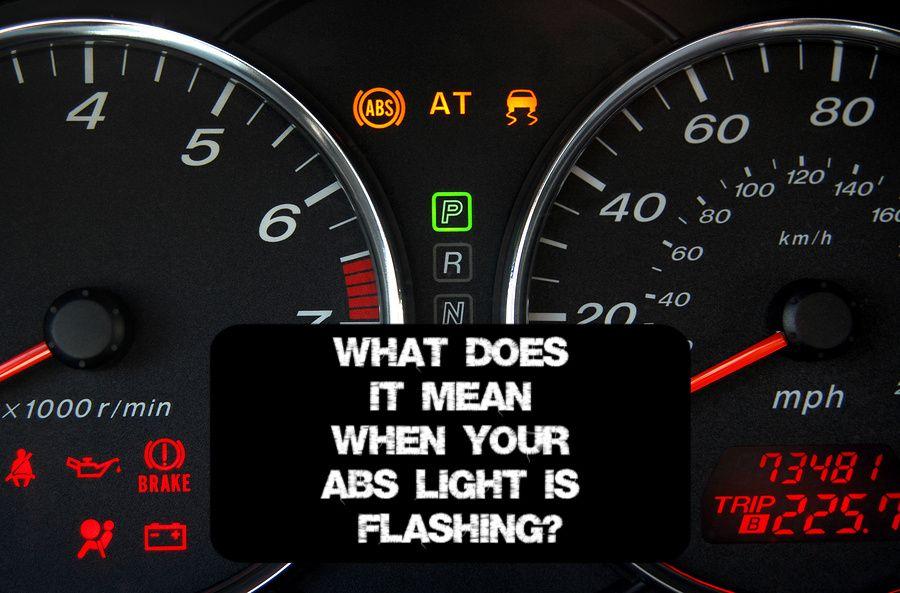
Alright, let's talk about that dreaded ABS light staring you down from the dashboard. Seeing it illuminate is never a good feeling, but understanding what it signifies and how the Anti-lock Braking System (ABS) functions can empower you to diagnose the issue or at least speak intelligently with your mechanic. This guide is aimed at the DIY enthusiast who wants a deeper dive than just "take it to the shop."
Purpose of Understanding the ABS System
Why bother learning about the ABS? Several reasons:
- Informed Repairs: Knowing the components and their interactions helps you accurately diagnose ABS problems, potentially saving money on unnecessary repairs.
- Improved Safety: Understanding how ABS works allows you to drive more effectively in emergency braking situations.
- Modifications: If you're considering any modifications to your braking system (e.g., bigger brake rotors, performance pads), understanding ABS interaction is crucial.
- General Automotive Knowledge: It's just good to know how a critical safety system in your car operates!
We're going to cover the key components, how they interact, and basic troubleshooting. And importantly, we have a full ABS system wiring diagram available for download – just look for the link at the end of this article. Having that diagram will be immensely helpful when you're chasing electrical gremlins.
Key Specs and Main Parts
The ABS is a complex system that relies on several interconnected components. Here's a breakdown of the major players:
- Wheel Speed Sensors (WSS): These sensors are typically located near each wheel hub and monitor the rotational speed of each wheel. They are usually magnetic or hall-effect sensors. A magnetic sensor uses a toothed rotor and a coil; as the wheel spins, the teeth pass by the coil, generating a signal proportional to wheel speed. A hall-effect sensor uses a similar rotor but relies on the Hall effect to generate the signal.
- ABS Control Module (ECU): The "brain" of the ABS. It receives data from the wheel speed sensors, analyzes it, and controls the hydraulic modulator. This is a computer, so it can also store diagnostic trouble codes (DTCs) when it detects a fault.
- Hydraulic Modulator Unit (HMU): This is the heart of the system. It contains valves and a pump that control brake pressure to each wheel independently. During an ABS event, the HMU cycles these valves rapidly to prevent wheel lock-up.
- Brake Pressure Sensors: Some systems use brake pressure sensors within the HMU to provide feedback to the ECU about the actual pressure being applied to each brake circuit. This helps the ECU fine-tune the ABS intervention.
- ABS Warning Light: The light on your dashboard – it's the messenger. It illuminates when the ECU detects a fault in the ABS system. It's triggered when the ECU detects a DTC.
- Brake Pedal Position Sensor: Some advanced ABS systems (often integrated with stability control) also use a brake pedal position sensor to determine how hard the driver is pressing the brake pedal. This information helps the ECU anticipate and react to braking situations.
- Wiring Harness: All these components are connected by a network of wires, often bundled into a dedicated harness. Damaged wiring or corroded connectors can cause ABS problems.
Symbols and Diagram Interpretation
A wiring diagram uses standardized symbols and lines to represent components and connections. Let's break down some of the key elements:
- Lines: Solid lines typically represent wires. Thicker lines might indicate wires carrying more current or higher voltage. Dashed lines can represent shielded cables or communication buses (e.g., CAN bus).
- Colors: Wires are often color-coded. A legend on the diagram will tell you what each color represents (e.g., red for power, black for ground). Always refer to the legend – color codes can vary between manufacturers.
- Icons: Specific icons represent components. A circle with an "S" inside might be a sensor, while a rectangle with a "C" inside could be a connector. Again, the diagram's legend is your best friend.
- Ground Symbols: Various symbols represent ground connections. A three-tiered ground is common, but there are others. Ensure the ground points in your system are clean and making good contact.
- Connectors: Connectors are usually depicted as interlocking shapes. Pay close attention to connector pin numbers – these are critical for testing and troubleshooting.
Understanding these symbols is key to tracing circuits and identifying potential problems within the ABS system.
How It Works
Here's the core functionality of the ABS:
- Normal Braking: Under normal braking conditions, the ABS system is passive. Brake fluid flows from the master cylinder, through the HMU, and to the brakes, just like in a non-ABS system.
- Impending Lock-up Detection: The wheel speed sensors continuously monitor the rotational speed of each wheel. If one or more wheels start to decelerate rapidly – indicating an impending lock-up – the ECU kicks in.
- Pressure Modulation: The ECU signals the HMU to rapidly cycle valves that control brake pressure to the affected wheel(s). This cycling happens multiple times per second, preventing the wheel from locking up. The HMU can either:
- Reduce pressure to the wheel.
- Hold pressure to the wheel.
- Increase pressure to the wheel.
- Maintaining Steering Control: By preventing wheel lock-up, the ABS allows the driver to maintain steering control during hard braking. This is because a rolling wheel provides significantly more lateral grip than a sliding wheel.
The key is that the ABS system *doesn't* necessarily shorten stopping distances in all situations. Its primary function is to maintain steering control. In some cases (e.g., on loose gravel or snow), ABS might actually slightly *increase* stopping distance. However, the increased ability to steer around obstacles more than compensates for this.
Real-World Use – Basic Troubleshooting
If your ABS light is on, here are some basic troubleshooting steps you can take before heading to a mechanic:
- Visual Inspection: Check all wheel speed sensor wires for damage. Look for cuts, abrasions, or corrosion. Inspect the connectors at the sensors and the HMU. Clean any corroded connections with electrical contact cleaner.
- Scan for Codes: Use an OBD-II scanner to retrieve ABS diagnostic trouble codes (DTCs). These codes will provide clues about the source of the problem. Write down the codes and research them thoroughly. Note that generic OBD-II scanners might not read ABS-specific codes; you might need a more advanced scanner.
- Check Wheel Speed Sensors: Using a multimeter, you can test the wheel speed sensors. Check their resistance and signal output as the wheel is rotated. Consult your vehicle's service manual for specific testing procedures and resistance values.
- Check Fuses: Locate the fuse for the ABS system and check if it's blown. Replace it with a fuse of the correct amperage. If the fuse blows again immediately, there's a short circuit in the system that needs to be investigated.
- Check Grounds: Inspect the ground connections for the ABS ECU and HMU. Ensure they are clean, tight, and free of corrosion.
Example Troubleshooting Scenario: You get a code indicating a faulty wheel speed sensor. After visual inspection, you notice a broken wire near the sensor. Repairing the wire might resolve the issue. If not, you could test the sensor with a multimeter. If the sensor tests bad, replacing it should fix the problem.
Safety
The ABS system contains several components that can be dangerous if mishandled. Always take the following precautions:
- Depressurize the System: Before working on any hydraulic components of the ABS (e.g., the HMU or brake lines), depressurize the system according to the manufacturer's instructions. This usually involves disconnecting the battery and pumping the brake pedal several times.
- Avoid Electrical Shocks: The ABS ECU and HMU operate on electrical power. Disconnect the battery before working on any electrical components.
- Brake Fluid: Brake fluid is corrosive. Wear eye protection and gloves when handling it. Clean up any spills immediately.
- High-Pressure Components: The HMU contains high-pressure valves and pumps. Never attempt to disassemble it yourself unless you have specialized training and equipment.
Important Note: Improper repairs to the ABS system can compromise its functionality and create a safety hazard. If you're not comfortable working on the ABS system, it's best to take your vehicle to a qualified mechanic.
We've covered a lot here. Remember, having the right information and a systematic approach is key to tackling ABS issues. And as promised, you can download a detailed ABS wiring diagram to aid your troubleshooting. We have the file ready for you.