What Does A Stick Shift Look Like
Let's dive into the anatomy of a stick shift, or manual transmission gear selector. Whether you're diagnosing a balky gearbox, contemplating a short-throw shifter upgrade, or simply want a deeper understanding of how your car works, knowing the intricacies of the stick shift mechanism is invaluable. This article will provide a detailed look at its components, operation, and potential problem areas. Understanding this is crucial for anyone involved in repairs, modifications, or even basic troubleshooting of a manual transmission system. We'll treat this like a diagram breakdown, explaining each element and its function.
Key Specs and Main Parts
The stick shift, or gear selector, is the driver's direct interface with the transmission's internal workings. Its primary function is to select the desired gear ratio, which in turn dictates the engine's output speed relative to the wheels' speed. The fundamental parts involved are:
- Shift Knob: The handle the driver grips.
- Shift Lever (or Stick): The metal rod extending from the knob downwards.
- Shift Linkage: A system of rods, cables, or a combination of both that connects the shift lever to the transmission's shift forks.
- Shift Forks: Internal components within the transmission that engage and disengage gears on the mainshaft.
- Detent Mechanism: A system of springs and ball bearings (or similar mechanisms) that provide tactile feedback and help hold the shift lever in the selected gear position.
- Shift Rails (or Selector Shafts): Rods inside the transmission upon which the shift forks slide, each connected to a specific gear selection.
Modern manual transmissions also often include interlock mechanisms that prevent the simultaneous engagement of multiple gears, protecting the transmission from damage. Older designs, especially in heavy-duty applications, might use more robust and mechanically simpler linkages.
Symbols and Representation in Diagrams
Technical diagrams depicting stick shifts and shift linkages employ several conventions to represent different components and their interactions:
- Solid Lines: Typically represent rigid components such as rods, levers, and the shift lever itself.
- Dashed Lines: Often indicate hidden or internal components, or represent the *path* of motion rather than a physical component. For example, a dashed line might trace the movement of a shift fork inside the transmission housing.
- Arrows: Indicate the direction of movement or force. An arrow on a linkage might show the direction in which a force is being applied to actuate a shift rail.
- Circles and Spheres: Commonly depict pivot points or ball joints within the linkage.
- Colors (when used): May be used to differentiate between different components or systems. For example, one color might represent the linkage for first and second gear, while another color represents the linkage for third and fourth gear.
- Icons: Standardized symbols may be used to represent specific parts like springs (zigzag lines), bearings (circles with a cross inside), or fasteners (nuts, bolts, and screws depicted schematically).
- Labels: Every component should have a label, usually an abbreviated term or a number corresponding to a key in the diagram's legend.
It's critical to pay attention to the legend or key accompanying the diagram. This explains the meaning of each symbol, line type, and color used. Without it, the diagram is nearly unintelligible.
How It Works: From Hand to Gear
The operation of a stick shift, at its core, involves translating the driver's hand movements into the precise engagement of gears within the transmission. The process can be broken down into these steps:
- Driver Input: The driver moves the shift lever to the desired gear position.
- Linkage Activation: This movement is transmitted through the shift linkage (rods, cables, or a combination) to the transmission. The mechanical advantage of the linkage design can influence the force required to shift.
- Shift Fork Engagement: The linkage, connected to the shift rails inside the transmission, moves the corresponding shift fork.
- Gear Engagement: The shift fork slides along the shift rail and engages a synchronizer (synchro) ring. The synchronizer's job is to match the speed of the gear to the speed of the output shaft before the gear is fully engaged. This prevents grinding.
- Full Engagement: Once the speeds are synchronized, the shift fork fully engages the gear, locking it to the output shaft.
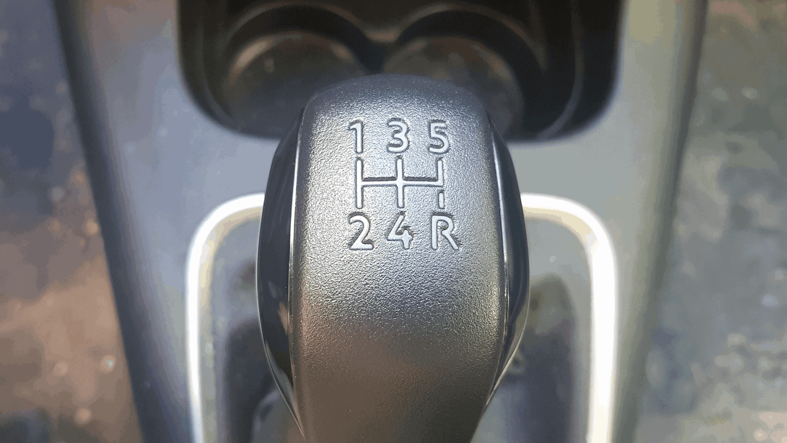
The H-pattern (or other pattern depending on the transmission) of the shift lever dictates which shift rail is selected for each gear. The detent mechanism ensures the lever stays in the selected gear by providing resistance to movement and then a satisfying "click" as it locks into position.
Real-World Use and Basic Troubleshooting
Understanding the stick shift mechanism can be invaluable for diagnosing common problems:
- Difficulty Shifting: Could be due to worn or damaged shift linkage components (e.g., loose ball joints, bent rods), a misadjusted clutch cable (if applicable), or internal transmission problems (e.g., worn synchronizers, bent shift forks).
- Grinding Gears: Typically indicates worn or damaged synchronizers. The synchro rings are not able to match the gear speeds quickly enough, causing the gears to clash.
- Sticking Shifter: Could be caused by a binding shift linkage, a worn detent mechanism, or internal transmission damage.
- Slop in Shifter: Often caused by wear in the shift linkage, particularly at the ball joints or bushings.
- Shifter Popping Out of Gear: Can be caused by worn detent mechanisms, bent shift forks, or excessive wear on the gear teeth themselves.
Troubleshooting Tip: Start by inspecting the shift linkage for any obvious signs of damage or wear. Check for loose connections, bent rods, and worn bushings. Lubricating the linkage can sometimes alleviate minor binding issues. If the problem persists, further investigation of the internal transmission components may be required.
Safety: Highlight Risky Components
Working on a manual transmission system can be hazardous. Here are some key safety considerations:
- Transmission Fluid: Some transmission fluids can be corrosive or toxic. Always wear gloves and eye protection when handling them.
- Springs: Detent mechanisms and other parts of the transmission often contain strong springs. These can be under significant tension and can cause injury if released improperly. Always use appropriate tools and techniques to safely compress and release springs.
- Sharp Edges: Many transmission components have sharp edges. Wear gloves to protect your hands.
- Proper Support: Never work under a vehicle supported only by a jack. Always use jack stands.
- Torque Specs: When reassembling components, always use the correct torque specifications to ensure proper functionality and prevent damage.
It's important to remember that working on a transmission requires a good understanding of mechanical principles and access to specialized tools. If you are not comfortable performing a particular task, it is best to consult a qualified mechanic.
We have a detailed diagram illustrating the stick shift mechanism available for download. This diagram includes labeled components, exploded views, and cutaway illustrations to provide a comprehensive understanding of the system. This resource can be a valuable aid for repairs, modifications, and general learning. Understanding the forces at play and the interactions between the components is essential for effective diagnosis and repair. Furthermore, knowledge of the materials used – steel, aluminum, polymers – can inform your choice of replacement parts or modifications.