What Does Abs Light In Car Mean
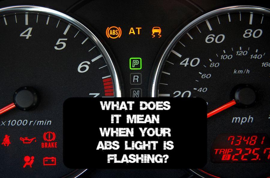
The dreaded ABS light glowing on your dashboard – it's a sign something isn't quite right with your Anti-lock Braking System. Ignoring it can lead to reduced braking performance, especially in emergency situations. Understanding what that light means, and the system behind it, can empower you to diagnose and potentially fix the issue yourself, saving money and gaining valuable automotive knowledge. This article dives deep into the ABS system, focusing on interpreting its operation and basic troubleshooting steps.
Purpose of Understanding the ABS System
Delving into the ABS system isn't just about fixing a lit-up dashboard light. It's about:
- Enhanced Safety: Properly functioning ABS can dramatically improve your vehicle's stopping ability in slippery conditions.
- Informed Repairs: Knowing the system's components and how they interact allows for more targeted and effective repairs.
- Cost Savings: Diagnosing simple issues yourself can prevent unnecessary trips to the mechanic.
- Preventative Maintenance: Understanding how the system works allows you to proactively identify potential problems before they become major headaches.
- Vehicle Modification Awareness: If you're modifying your brakes or suspension, understanding the ABS system is crucial to ensure compatibility and safety.
Key Specs and Main Parts
The ABS system is a complex network of sensors, actuators, and a central control unit. Here's a breakdown of the key components:
- Wheel Speed Sensors (WSS): These sensors are located at each wheel and continuously monitor the wheel's rotational speed. They're typically either inductive or Hall-effect sensors. An inductive sensor generates a signal based on a rotating toothed wheel (reluctor ring) passing by a coil. A Hall-effect sensor uses a magnetic field and a semiconductor to produce a voltage signal related to wheel speed.
- ABS Control Module (ECU): The ECU, or Electronic Control Unit, is the brains of the operation. It receives data from the wheel speed sensors, compares it to pre-programmed values, and determines if any wheels are locking up. It then commands the hydraulic modulator to adjust brake pressure accordingly.
- Hydraulic Modulator (HCU): This component controls the brake pressure applied to each wheel individually. It contains a series of valves and a pump. The valves, typically solenoid-operated, open and close to increase, decrease, or hold brake pressure. The pump recirculates brake fluid to maintain pressure.
- Brake Booster & Master Cylinder: While not exclusively part of the ABS system, these components provide the initial hydraulic pressure needed for braking. The brake booster uses vacuum from the engine (or an electric pump in some vehicles) to amplify the force applied to the brake pedal. The master cylinder converts this force into hydraulic pressure that is distributed to the brake calipers and wheel cylinders.
- Brake Lines & Hoses: These carry the brake fluid from the master cylinder, through the HCU, and to the brakes at each wheel.
- ABS Warning Light: Located on the instrument panel, this light illuminates when the ABS ECU detects a fault within the system.
Understanding ABS System Symbols and Wiring Diagrams
Wiring diagrams are crucial for diagnosing electrical faults in the ABS system. Here's a basic overview of common symbols and conventions:
- Lines: Solid lines represent wires. Thicker lines might indicate power wires. Dashed lines often represent grounding wires or signal wires.
- Colors: Wires are typically color-coded. The key will tell you what each color represents. For example, a red wire might be for +12V power, while a black wire is for ground.
- Ground Symbols: These symbols (often a series of descending horizontal lines or a triangle pointing downwards) indicate connection to the vehicle's chassis ground.
- Component Symbols: Each component (sensor, ECU, modulator, etc.) has a specific symbol. A legend accompanies the diagram to identify these symbols. Wheel speed sensors are often represented as inductive coils or rectangles with sensor elements. The ECU is usually depicted as a rectangle with pins representing input/output connections. The HCU can be more complex, showing solenoid valves, a pump, and fluid reservoirs.
- Connectors: Connectors are typically represented by interlocking shapes, indicating where wires connect and disconnect.
- Numbers and Letters: These identify wire gauge, circuit numbers, and terminal locations.
Key Specs: Understanding the wiring diagram also includes knowing the voltage and amperage ratings of various circuits within the ABS system. This information is vital when using a multimeter to test for continuity, voltage drops, or current draw. Consult your vehicle's service manual for specific electrical specifications.
How the ABS System Works
The ABS system's primary function is to prevent wheel lockup during braking, allowing the driver to maintain steering control. Here's how it works:
- Monitoring: The wheel speed sensors constantly monitor the rotational speed of each wheel.
- Data Analysis: The ABS ECU receives signals from all the wheel speed sensors. It compares the wheel speeds and looks for signs of imminent wheel lockup (a rapid deceleration of a wheel compared to the others).
- Pressure Modulation: If the ECU detects a wheel is about to lock up, it signals the hydraulic modulator to intervene. The modulator rapidly adjusts the brake pressure to that wheel, cycling the pressure up, down, and holding it. This happens very quickly, several times per second.
- Driver Feedback: The driver typically feels a pulsing sensation in the brake pedal as the modulator adjusts the brake pressure. This is normal.
- System Self-Check: The ABS ECU performs a self-check every time the vehicle is started. If it detects a fault, it illuminates the ABS warning light on the dashboard.
Real-World Use: Basic Troubleshooting Tips
Before attempting any repairs, always consult your vehicle's service manual for specific procedures and torque specifications.
- Check the Basics: Start by checking the brake fluid level. Low brake fluid can sometimes trigger the ABS light. Also, visually inspect the wheel speed sensor wiring for damage.
- Scan for Codes: Use an OBD-II scanner that can read ABS codes. This will provide valuable information about the specific problem. Common codes relate to wheel speed sensors, the hydraulic modulator, or the ECU.
- Wheel Speed Sensor Diagnosis:
- Resistance Test: Use a multimeter to measure the resistance of each wheel speed sensor. Compare the readings to the specifications in your service manual. An open circuit or a reading outside the specified range indicates a faulty sensor.
- Signal Check: With the wheel spinning (carefully raise the vehicle and spin the wheels by hand, or have an assistant slowly drive the vehicle while monitoring), use a multimeter or oscilloscope to check for a signal from each sensor. The signal should vary with wheel speed.
- Fuse Check: Check the ABS fuse in the fuse box. A blown fuse can disable the entire system.
- Wiring Inspection: Carefully inspect the wiring harness for the ABS system, looking for damaged wires, corroded connectors, or loose connections.
Example: Code C0035 indicates a problem with the front right wheel speed sensor. This could be a faulty sensor, a damaged wiring harness, or a problem with the reluctor ring. You would start by visually inspecting the sensor and wiring. If that looks good, you would then test the sensor's resistance and signal output.
Safety Considerations
Working on the ABS system involves handling brake fluid and electrical components. Exercise caution and follow these safety guidelines:
- Brake Fluid: Brake fluid is corrosive and can damage paint. Wear eye protection and gloves when handling it. Wipe up any spills immediately.
- Electrical System: Disconnect the negative battery cable before working on any electrical components of the ABS system.
- Airbags: Be aware of the location of airbags and their associated sensors and wiring. Avoid disturbing these components, as accidental airbag deployment can cause serious injury.
- High-Pressure System: The hydraulic modulator contains pressurized brake fluid. Do not attempt to disassemble it without proper training and equipment.
Risky Components: The hydraulic modulator and the ABS ECU are the most complex and expensive components of the system. Repairs to these components are often best left to a qualified technician.
We have a detailed wiring diagram of a generic ABS system available for download. This diagram provides a visual representation of the system's components and their connections. It can be a valuable tool for diagnosing and repairing ABS problems. Contact us to get access to the file.
Disclaimer: This article provides general information about ABS systems and basic troubleshooting tips. It is not a substitute for professional automotive advice. Always consult your vehicle's service manual and follow proper safety procedures when working on your vehicle. If you are not comfortable performing any of these tasks, seek the assistance of a qualified mechanic.