What Does Abs Light Mean In Car
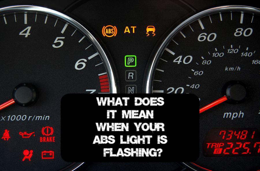
So, your ABS light is on. That little amber glow on your dash can be intimidating, but don't panic. While it *does* indicate a problem with your Anti-lock Braking System (ABS), understanding the system and the light itself can empower you to diagnose and potentially fix the issue yourself. This article will dive deep into the ABS system, focusing on what that light *really* means and how to approach troubleshooting.
Purpose of Understanding the ABS Light and System
Why bother digging into the ABS when a mechanic can handle it? Because knowledge is power, especially when it comes to your car. Understanding the ABS system is crucial for several reasons:
- Informed Repairs: Knowing the components and how they interact allows you to discuss repairs intelligently with your mechanic, preventing unnecessary work and costs.
- DIY Troubleshooting: Many ABS problems are relatively simple to diagnose and fix with the right tools and knowledge. Save money by identifying the issue yourself.
- Performance Tuning: If you're into performance driving or modifying your car, understanding how the ABS interacts with other systems is critical for optimizing its behavior.
- Safety Awareness: A faulty ABS can compromise your braking performance, especially in adverse conditions. Recognizing the symptoms early can prevent accidents.
Key Specs and Main Parts of the ABS System
Let's break down the core components of a typical ABS system. Keep in mind that specific designs can vary slightly between manufacturers and models.
Main Components:
- Wheel Speed Sensors (WSS): These sensors, typically located near each wheel hub, monitor the rotational speed of each wheel. They send this data to the ABS control module.
- ABS Control Module (ECU or Module): The "brain" of the system. It receives data from the WSS, determines if a wheel is locking up during braking, and controls the hydraulic modulator. This is often called the EBCM (Electronic Brake Control Module).
- Hydraulic Modulator (ABS Pump/Valve Block): This unit contains valves and a pump that control the brake pressure to each wheel. When a wheel is about to lock up, the modulator rapidly reduces, holds, and increases pressure to allow the wheel to continue rotating.
- Brake Lines and Hoses: These are the conduits for brake fluid, connecting the master cylinder to the hydraulic modulator and then to each wheel's brake caliper.
- ABS Warning Light: Located on your instrument panel, this light illuminates when the ABS system detects a fault.
Key Specs to Consider:
- Sensor Type: Wheel speed sensors can be inductive or Hall-effect. Inductive sensors generate a voltage signal based on a rotating toothed ring, while Hall-effect sensors use a magnetic field to detect wheel speed.
- Operating Voltage: The ABS module and sensors typically operate on a 12V system.
- Diagnostic Trouble Codes (DTCs): When the ABS light comes on, the system stores DTCs that pinpoint the specific problem. These codes can be read using an OBD-II scanner.
- Brake Fluid Type: Using the correct brake fluid (DOT 3, DOT 4, or DOT 5.1) is crucial for proper ABS function and longevity.
Understanding ABS System Diagrams
Schematic diagrams are your roadmap for understanding how the ABS system is wired and plumbed. Let's decipher some common elements:
Symbols and Conventions:
- Lines: Solid lines usually represent electrical wires. Dashed lines might represent hydraulic lines (brake fluid).
- Colors: Wire colors are often indicated next to the lines (e.g., "GRN" for green, "BLU" for blue). Matching wire colors in the diagram to the actual wires in your car is essential for accurate diagnosis.
- Icons:
- Circles with "X" inside: Often represents a sensor.
- Rectangles: Commonly represent relays, modules, or solenoids.
- Ground Symbol (⏚): Indicates a ground connection.
- Numbers: Pins on connectors and components are usually numbered.
Diagrams show the electrical connections between the ABS module, wheel speed sensors, hydraulic modulator, and other related components. They also often include hydraulic schematics showing the internal workings of the modulator.
How the ABS System Works
During normal braking, the ABS system remains passive. The ECU continuously monitors the wheel speed sensors. However, when the ECU detects that one or more wheels are decelerating rapidly (a sign of impending lockup), it kicks into action:
- Detection: The ECU analyzes the wheel speed data. If a wheel's speed drops significantly faster than the others, the ECU identifies it as a wheel that's about to lock up.
- Pressure Modulation: The ECU signals the hydraulic modulator to reduce brake pressure to the affected wheel. This is done by opening and closing valves within the modulator.
- Pressure Cycling: The modulator rapidly cycles the brake pressure, reducing, holding, and then reapplying it. This allows the wheel to continue rotating, maintaining traction and steering control.
- Repeat: The process repeats as needed until the driver releases the brake pedal or the wheel recovers its speed.
This rapid cycling of brake pressure is what causes the pulsating sensation you feel in the brake pedal when the ABS is engaged. This pulsation is normal and indicates that the system is working correctly.
Real-World Use: Basic Troubleshooting Tips
Okay, so the ABS light is on. Here's how to approach troubleshooting:
- Check the Basics: Ensure that your brake fluid level is correct and that there are no visible leaks in the brake lines or around the wheel cylinders/calipers.
- OBD-II Scan: Use an OBD-II scanner to retrieve the DTCs stored by the ABS module. This will give you a specific direction to investigate.
- Research the DTC: Once you have the DTC, research it online. Common ABS problems include faulty wheel speed sensors, a malfunctioning hydraulic modulator, or wiring issues.
- Inspect Wheel Speed Sensors: Visually inspect the wheel speed sensors and their wiring for damage, corrosion, or loose connections. Clean the sensor and the toothed ring it reads from. Use a multimeter to check the sensor's resistance or voltage output.
- Check Wiring and Connectors: Inspect the wiring harness and connectors associated with the ABS system for damage, corrosion, or loose connections. Pay particular attention to connectors near the wheels, as they are exposed to harsh conditions.
- Test the Hydraulic Modulator: Testing the hydraulic modulator typically requires specialized equipment and knowledge. This is often best left to a professional.
Example: A common DTC is "C0035 - Left Front Wheel Speed Sensor Circuit." This indicates a problem with the left front wheel speed sensor. Check the sensor's wiring, connector, and the sensor itself. Replacing the sensor is often the solution.
Safety Precautions
Working on the ABS system involves dealing with brake fluid and electrical components. Always take the following precautions:
- Brake Fluid: Brake fluid is corrosive and can damage paint and skin. Wear gloves and eye protection when handling it. Wipe up any spills immediately.
- Electrical System: Disconnect the negative battery terminal before working on any electrical components of the ABS system. This prevents accidental shorts and electrical shocks.
- Hydraulic System: When working on the hydraulic system, be aware that it is under pressure. Depressurize the system before disconnecting any brake lines.
- Risk of Fire: Some components, especially near the hydraulic modulator, could have a very small chance of leaking brake fluid onto a hot engine component. Make sure everything is clean and dry before starting the engine.
Note: If you're not comfortable working on the braking system, it's always best to consult a qualified mechanic. Improper repairs can compromise your safety and the safety of others.
By understanding the function and construction of your ABS system, you can diagnose and repair common issues. Remember to always consult your vehicle's repair manual for specific procedures and torque specifications. We have the full detailed schematic diagram for many vehicle makes, and can provide you with a copy. Understanding the diagram and understanding your vehicle are key to proper repairs.