What Does Abs Mean On Dashboard
Alright, let's dive into that little ABS light on your dashboard. It might seem like a minor annoyance, but understanding what it means is crucial for your safety and your car's performance. We're going to break down the Anti-lock Braking System (ABS), what that warning light signifies, and how to troubleshoot some common issues. This knowledge is invaluable whether you're planning on tackling minor repairs yourself, understanding your car's system better, or simply want to be an informed car owner.
Purpose of Understanding the ABS Warning Light
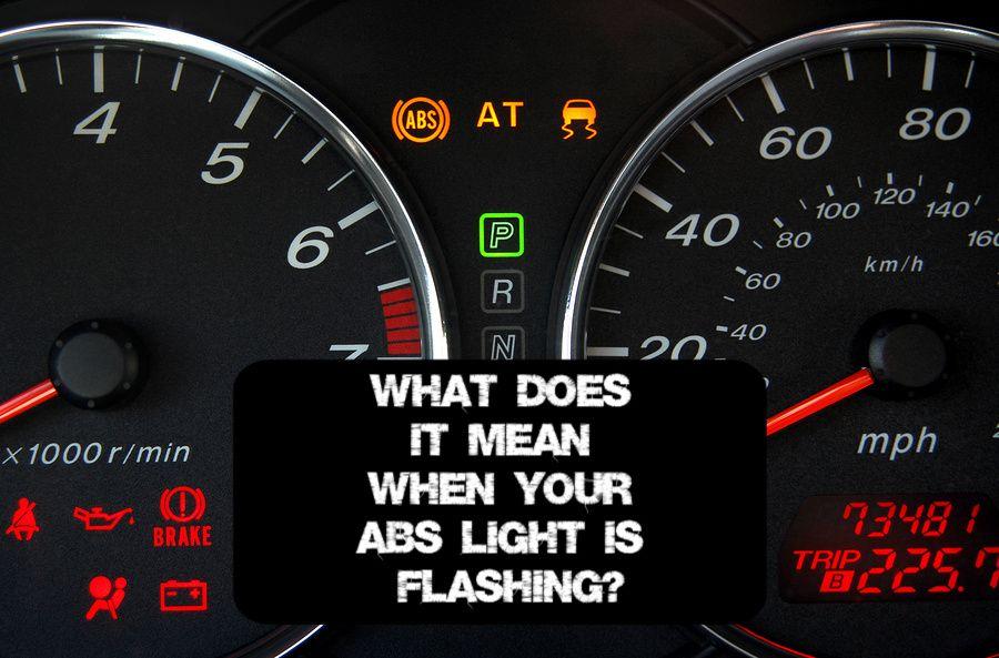
Why should you care about this ABS light? Well, a functioning ABS is a critical safety feature. It prevents your wheels from locking up during hard braking, allowing you to maintain steering control and potentially avoid accidents. When the ABS light illuminates, it indicates that the system has detected a fault and has deactivated itself. This means your brakes will still function normally, but without the anti-lock functionality. Driving without ABS, especially in wet or icy conditions, significantly increases your stopping distance and the risk of skidding. Therefore, addressing the issue that triggered the ABS light is paramount for safe driving.
Understanding the system and its components can also save you money. Diagnosing the problem yourself can prevent unnecessary trips to the mechanic. Plus, if you’re a DIYer, knowing the system’s architecture lets you troubleshoot the problem yourself, or give more accurate information to your mechanic.
Key Specs and Main Parts of an ABS
Let's look under the hood, metaphorically speaking. The ABS consists of several key components that work together to prevent wheel lockup. These components include:
- Wheel Speed Sensors: These sensors, typically located at each wheel hub, constantly monitor the rotational speed of the wheels. They send this information to the ABS control module. A common type is a variable reluctance sensor, creating an AC signal dependent on the wheel’s rotational speed.
- ABS Control Module (ECU): This is the brain of the system. It receives signals from the wheel speed sensors, analyzes the data, and determines when a wheel is about to lock up. If a lockup is imminent, it activates the hydraulic modulator.
- Hydraulic Modulator: This unit contains a series of valves and a pump that control the brake pressure to each wheel. When the control module detects a wheel lockup, the modulator rapidly reduces, holds, or increases brake pressure to that wheel, allowing it to continue rotating and maintain traction.
- Brake Lines and Calipers: These are standard braking system components, but they are integrated with the ABS hydraulic modulator to allow for individual wheel brake pressure control.
- ABS Pump/Motor: Used to replenish brake fluid pressure. When brake fluid pressure is released during ABS activation, the pressure needs to be built back up for the next cycle.
The system operates on a 12V DC power supply, and the control module usually has multiple inputs and outputs, connected through a wiring harness. Resistance and voltage are important metrics when testing the system components. Wheel speed sensors, for instance, will output different voltages dependent on wheel speed.
Symbols, Lines, Colors, and Icons in an ABS Diagram
When looking at an ABS wiring diagram, it's important to understand the symbols and conventions used. Standard symbols are used to represent components like sensors, actuators, relays, and fuses. These symbols conform to common automotive electrical diagramming standards. Here are some examples:
- Lines: Solid lines represent wires, while dashed lines might indicate a shielded wire or a connection within a module. Wire thickness (gauge) might also be shown.
- Colors: Wires are typically color-coded, and a key will be provided on the diagram indicating the color of each wire and its function (e.g., Blue/White – Wheel Speed Sensor Signal).
- Icons: Specific icons represent different components. For instance, a wheel speed sensor might be depicted as a coil with a toothed wheel nearby. The ABS control module will often be depicted as a rectangle with pins representing the inputs and outputs.
- Numbers/Letters: These are used to identify specific wires, connectors, or pins within the system.
Common color coding includes black for ground, red for power, and other colors for signal wires. It is crucial to refer to the specific wiring diagram for your vehicle, as color-coding can vary between manufacturers and models.
How ABS Works: The Process
The ABS system works in a closed-loop feedback control system. Here's a breakdown:
- Monitoring: The wheel speed sensors constantly monitor the rotational speed of each wheel.
- Data Processing: The ABS control module receives these signals and compares them to determine if any wheel is decelerating abnormally quickly, which indicates an impending lockup. This is done using sophisticated algorithms that take into account vehicle speed, deceleration rate, and other factors.
- Actuation: If the control module detects a potential lockup, it signals the hydraulic modulator to intervene. The modulator contains valves that can independently control the brake pressure to each wheel.
- Pressure Modulation: The modulator rapidly reduces, holds, or increases brake pressure to the affected wheel, preventing it from locking up. This process can occur multiple times per second. The driver might feel a pulsing sensation in the brake pedal during ABS activation, which is normal.
- Feedback: The wheel speed sensors continue to monitor the wheel speed, and the control module adjusts the brake pressure accordingly, maintaining optimal braking performance while preventing wheel lockup.
The entire process happens in milliseconds, allowing the driver to maintain steering control during emergency braking situations.
Real-World Use: Basic Troubleshooting Tips
If your ABS light is on, don't panic. Here are some basic troubleshooting steps you can take:
- Check Brake Fluid Level: A low brake fluid level can sometimes trigger the ABS light. Top it off, but also investigate the source of the leak.
- Inspect Wheel Speed Sensors: Visually inspect the sensors and their wiring for damage, corrosion, or loose connections. Use a multimeter to test the sensor resistance. Refer to your vehicle's repair manual for the correct resistance values.
- Scan for Diagnostic Trouble Codes (DTCs): Use an OBD-II scanner to retrieve the fault codes stored in the ABS control module. These codes can provide valuable clues about the source of the problem. Common codes include sensor failures, modulator issues, or control module malfunctions.
- Check Fuses and Relays: Inspect the fuses and relays related to the ABS system. A blown fuse or a faulty relay can prevent the system from functioning correctly.
Important Note: While you can perform basic troubleshooting, more complex ABS issues might require specialized equipment and expertise. If you're not comfortable working with electrical systems or brake components, it's best to consult a qualified mechanic.
Safety Considerations
Working on the ABS system involves dealing with both electrical and hydraulic components, which can be dangerous if not handled properly. Here are some key safety precautions:
- Disconnect the Battery: Always disconnect the negative battery terminal before working on any electrical components of the ABS system. This will prevent accidental shorts and potential injuries.
- Depressurize the Brake System: Before disconnecting any brake lines, make sure to depressurize the brake system. Consult your vehicle's repair manual for the proper procedure.
- Wear Safety Glasses and Gloves: Brake fluid is corrosive and can damage your eyes and skin. Always wear safety glasses and gloves when working with brake fluid.
- Proper Disposal of Brake Fluid: Dispose of used brake fluid properly. It is considered hazardous waste and should not be poured down the drain or into the environment.
- Be Cautious of High-Pressure Components: The hydraulic modulator contains high-pressure components. Avoid disassembling or tampering with these components unless you have the proper training and equipment.
Warning: Brake systems are critical safety components. If you are not comfortable working on them, it is best to consult a qualified mechanic.
We have a detailed ABS wiring diagram available for download. This diagram will provide you with the specific wiring information for your vehicle, including wire colors, connector locations, and component identification. It will be an invaluable resource for troubleshooting and repairing your ABS system.
Armed with this knowledge and the wiring diagram, you'll be in a much better position to understand and address any ABS issues that may arise. Remember, safety first, and don't hesitate to seek professional help when needed. Happy wrenching!