What Does Abs On Dashboard Mean
Alright, let's talk about that pesky ABS light on your dashboard. Seeing it pop up can be unsettling, but understanding what it represents and how the system works can empower you to diagnose and potentially address the issue yourself. This article breaks down the anti-lock braking system (ABS) warning light, the system behind it, and offers some basic troubleshooting tips. We'll cover everything from the key components to interpreting a simplified diagram. Why is this important? Because understanding your ABS can save you money on unnecessary repairs, help you learn more about your car's advanced systems, and contribute to safer driving.
Key Specs and Main Parts of an ABS System
The ABS system is designed to prevent wheel lockup during braking, allowing you to maintain steering control during emergency stops. It's a sophisticated system integrating several core components:
- Wheel Speed Sensors (WSS): These sensors, typically inductive or Hall-effect sensors, are mounted near each wheel. They constantly monitor the rotational speed of the wheel and send this data to the ABS control module. They are crucial for detecting wheel deceleration, a sign of impending lockup.
- ABS Control Module (ECU/Module): The brain of the ABS system. This electronic control unit receives data from the wheel speed sensors, analyzes it, and determines if any wheels are about to lock up. If lockup is detected, it commands the hydraulic control unit to modulate brake pressure.
- Hydraulic Control Unit (HCU): This unit, also known as the ABS pump or modulator, contains valves and a pump. Under the direction of the ABS control module, the HCU selectively increases, holds, or decreases brake pressure to individual wheels to prevent lockup. Think of it as a rapid and precise pressure regulator.
- Brake Lines and Calipers: Standard braking system components that deliver hydraulic pressure to the wheels. The ABS system works in conjunction with the existing brake system, not replacing it.
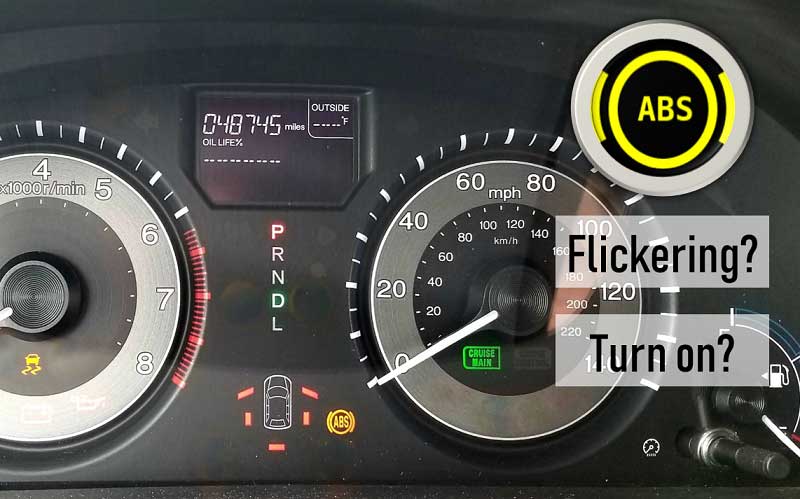
- ABS Warning Light: The indicator on your dashboard that alerts you to a potential problem within the ABS system.
Symbols: Decoding the Diagram
Understanding a basic ABS system diagram requires recognizing common symbols. Let's break down some typical representations:
- Solid Lines: Typically represent hydraulic brake lines carrying brake fluid under pressure.
- Dotted Lines: Often represent electrical wiring connecting the sensors, control module, and other components.
- Rectangles/Squares: Can represent various components like the ABS control module or individual valves within the HCU. The specific labeling will determine the exact component.
- Circles: Usually represent the wheel speed sensors, often with a small extension indicating the sensor’s position relative to the wheel’s rotating component (e.g., tone ring).
- Colors: While not standardized across all diagrams, some common conventions include:
- Red: High-pressure hydraulic lines.
- Blue: Low-pressure hydraulic lines or return lines.
- Black: Ground wires.
- Other Colors (e.g., Green, Yellow): Signal wires carrying data between sensors and the control module. Consult the specific diagram's legend.
- Icons: Pay attention to specific icons used to represent valves (solenoid valves, pressure relief valves), pumps, and reservoirs within the HCU. A legend accompanying the diagram is essential for accurate interpretation.
How the ABS System Works: A Step-by-Step Explanation
Here's a simplified explanation of how the ABS system functions during hard braking:
- Normal Braking: Under normal braking conditions, the brake pedal is depressed, and hydraulic pressure is applied to the brake calipers, slowing the vehicle. The ABS system remains passive.
- Wheel Speed Monitoring: The wheel speed sensors continuously monitor the rotational speed of each wheel and transmit this data to the ABS control module.
- Lockup Detection: If the ABS control module detects that one or more wheels are decelerating rapidly (indicating impending lockup), it initiates ABS intervention. Rapid deceleration means the wheel is slowing much faster than expected based on vehicle speed.
- Pressure Modulation: The ABS control module signals the hydraulic control unit to modulate brake pressure to the affected wheel(s). This modulation happens extremely quickly, up to several times per second. The HCU uses solenoid valves to achieve this.
- Pressure Reduction: The HCU reduces pressure to the wheel that is about to lock up.
- Pressure Holding: The HCU may hold the pressure at a certain level to prevent further lockup.
- Pressure Increase: If the wheel regains traction, the HCU will gradually increase pressure again to maximize braking force.
- Maintaining Steering Control: By preventing wheel lockup, the ABS system allows the driver to maintain steering control during emergency braking. The driver can steer around obstacles while still applying maximum braking force.
- Cycle Repeats: This cycle of pressure modulation repeats continuously until the vehicle comes to a stop or the driver releases the brake pedal. You may feel a pulsing sensation in the brake pedal during ABS activation, which is normal.
Real-World Use: Basic Troubleshooting Tips
If your ABS light illuminates, it indicates a problem within the system. Here are some basic troubleshooting steps you can take before consulting a professional mechanic:
- Check Brake Fluid Level: A low brake fluid level can sometimes trigger the ABS light. Top up the fluid if necessary, but be aware that a constantly low fluid level usually indicates a leak in the system.
- Inspect Wheel Speed Sensors: Visually inspect the wheel speed sensors for damage, loose connections, or debris. Clean the sensors if necessary. Check the wiring harness connected to the sensors for any signs of damage.
- Check ABS Fuses: Locate the fuse box (usually under the dashboard or in the engine compartment) and check the fuse(s) related to the ABS system. Replace any blown fuses with the correct amperage rating.
- OBD-II Scanner: Use an OBD-II scanner to retrieve diagnostic trouble codes (DTCs) related to the ABS system. These codes can provide valuable clues about the nature of the problem. Common codes relate to wheel speed sensors, the ABS control module, or hydraulic issues.
Important Note: Some ABS-specific codes may require a more advanced scanner capable of accessing the ABS module directly. A generic OBD-II scanner might only read generic powertrain codes.
- Test Drive (Carefully): After performing the above checks, take the vehicle for a short test drive (in a safe, controlled environment) to see if the ABS light clears. Try performing a simulated emergency stop to see if the ABS system activates correctly. If the light remains on, further diagnosis is required.
Safety: Highlighting Risky Components
Working on the ABS system involves dealing with high-pressure hydraulic fluid and sensitive electronic components. Here are some key safety precautions:
- Depressurize the System: Before disconnecting any brake lines, consult your vehicle's service manual for instructions on how to properly depressurize the braking system. Failure to do so can result in a spray of high-pressure brake fluid, which can be harmful.
- Brake Fluid: Brake fluid is corrosive and can damage painted surfaces. Wear eye protection and gloves when working with brake fluid. Clean up any spills immediately.
- Electrical Components: Be careful when working with electrical connectors and wiring. Disconnect the negative battery terminal before performing any electrical work on the ABS system to prevent shorts or damage to the control module.
- HCU: The Hydraulic Control Unit contains complex internal components. Do not attempt to disassemble or repair the HCU unless you have specialized knowledge and tools. Improper handling can damage the unit or cause injury.
- Professional Help: If you are not comfortable working with the ABS system or if you are unable to diagnose the problem, seek assistance from a qualified mechanic. The ABS system is critical for safety, and improper repairs can have serious consequences.
We have a simplified ABS system diagram available for download. This diagram provides a general overview of the system's components and their interconnections. While it may not be specific to your vehicle, it can be a valuable tool for understanding the basic principles of ABS operation.
By understanding the basic principles of ABS, you can be better prepared to address issues with your vehicle's braking system and ensure safer driving. Remember to always consult your vehicle's service manual for specific instructions and safety precautions.