What Does Acc Stand For In Cars
Understanding the electrical system of your car can seem daunting, but grasping the basics can empower you to tackle repairs, upgrades, and even diagnose problems yourself. One frequently encountered term in automotive electrical diagrams is ACC. This article will demystify what ACC stands for and how it functions within your car's electrical system, providing you with the knowledge to confidently navigate schematics and troubleshoot electrical issues.
What ACC Stands For
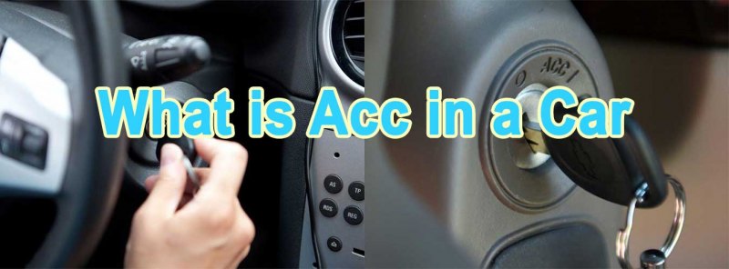
ACC stands for Accessory. In the context of your car, it refers to a specific position on the ignition switch that allows certain electrical components to operate without the engine running. Think of it as a 'pre-ignition' mode. This is the position you use when you want to listen to the radio, use the cigarette lighter (or power outlet), or operate other non-essential electrical devices without draining the battery while the engine is off.
Purpose – Why This Matters
Understanding the ACC circuit is crucial for several reasons:
- Troubleshooting Electrical Issues: If accessories aren't working when the key is in the ACC position, you can focus your troubleshooting efforts on the ACC circuit, including the ignition switch, associated fuses, relays, and wiring.
- Installing Aftermarket Accessories: Many aftermarket accessories, like stereos, dash cams, and auxiliary lighting, are designed to be powered by the ACC circuit. This ensures they only operate when the car is 'on' or in accessory mode, preventing battery drain.
- Reading Wiring Diagrams: ACC is a common label in automotive wiring diagrams. Knowing what it signifies allows you to trace circuits, identify components, and understand the flow of electricity.
- Preventing Battery Drain: The ACC position is specifically designed to power non-essential items. Knowing which devices are powered by this circuit helps prevent accidentally leaving something on and draining your battery.
Key Specs and Main Parts
The ACC circuit typically involves the following key components:
- Ignition Switch: This is the heart of the system. It's a multi-position switch that controls the flow of power to various circuits depending on the key position (Lock, ACC, On/Run, Start). The ignition switch has dedicated contacts for the ACC position.
- ACC Fuse: A fuse protects the ACC circuit from overloads. If too much current is drawn, the fuse will blow, interrupting the circuit and preventing damage to components. The amperage rating of the ACC fuse is crucial; replacing it with a higher amperage fuse can lead to fires.
- ACC Relay (Sometimes): Some vehicles utilize a relay to control the ACC circuit. A relay is an electrically operated switch that allows a low-current circuit (the ignition switch) to control a high-current circuit (the accessories). This protects the ignition switch from being overloaded.
- Wiring Harness: The wiring harness distributes power from the ignition switch (and relay, if present) to the various accessories connected to the ACC circuit.
- Accessories: These are the devices powered by the ACC circuit, such as the radio, cigarette lighter/power outlet, and certain control modules.
Symbols – Deciphering Wiring Diagrams
Automotive wiring diagrams use standardized symbols to represent electrical components and connections. Understanding these symbols is essential for interpreting the diagrams and tracing circuits.
- Lines: Solid lines represent wires. Dashed lines may represent shielded wires or wires bundled together.
- Colors: Wires are typically color-coded. A legend on the wiring diagram will indicate what each color represents. For example, a red wire might be a constant 12V power supply, while a yellow wire might be the ACC power supply.
- Fuses: Fuses are represented by a zigzag line within a box. The amperage rating of the fuse is often indicated next to the symbol.
- Relays: Relays are represented by a coil and a switch. The coil is energized when power is applied, which closes the switch and allows current to flow through the circuit.
- Ignition Switch: The ignition switch is represented by a series of contacts that connect different circuits depending on the key position. The ACC position will be clearly labeled.
- Grounds: Grounds are represented by a symbol resembling a downward-pointing triangle or a series of horizontal lines. Grounds provide a return path for current to flow back to the battery.
Learning to identify these symbols will empower you to follow the ACC circuit through the diagram and understand how it connects to other systems in the vehicle.
How It Works
When you turn the ignition key to the ACC position, the ignition switch closes a set of contacts specifically designed for the accessory circuit. This allows power to flow from the battery, through the ignition switch, through the ACC fuse (and possibly an ACC relay), and then to the various accessories connected to the circuit. The fuse protects the circuit from overloads, and the relay (if present) allows the ignition switch to control a higher current load without being damaged.
The key takeaway is that the ACC position provides power only to non-essential electrical devices, preserving battery power for starting the engine. When you turn the key to the 'On/Run' position, the ACC circuit remains active, and additional circuits are energized, providing power to the engine control unit (ECU), fuel pump, and other critical systems.
Real-World Use – Basic Troubleshooting Tips
Here are some basic troubleshooting tips for the ACC circuit:
- No Power to Accessories in ACC Position:
- Check the ACC fuse: This is the most common cause. Use a multimeter or test light to check for continuity across the fuse. A blown fuse should be replaced with one of the same amperage rating.
- Check the Ignition Switch: Use a multimeter to check for voltage at the ACC terminal of the ignition switch when the key is in the ACC position. If there's no voltage, the ignition switch may be faulty.
- Check the ACC Relay (if applicable): Use a multimeter to check for voltage at the relay coil when the key is in the ACC position. If there's voltage, but the relay isn't clicking, the relay may be faulty. Check the output side of the relay for voltage when the key is in the ACC position and the relay is energized.
- Check Wiring and Connections: Inspect the wiring harness for any signs of damage, such as frayed wires or loose connections. Use a multimeter to check for continuity between the ignition switch and the accessories.
- Battery Draining While Car is Off:
- Suspect ACC-powered devices: If you suspect a battery drain, check devices connected to the ACC circuit first. Ensure that devices like radios and phone chargers are fully off when the car is off.
- Parasitic Draw Test: A parasitic draw test, performed with a multimeter, can help identify if there's an excessive current draw from the battery when the car is off. This involves disconnecting the negative battery cable and measuring the current flowing between the cable and the battery terminal. A normal parasitic draw is typically less than 50 milliamps.
Safety – Handle with Care
Working with automotive electrical systems can be dangerous. Here are some safety precautions to keep in mind:
- Disconnect the Battery: Always disconnect the negative battery cable before working on any electrical components. This prevents accidental shorts and electrical shocks.
- Use Proper Tools: Use insulated tools designed for automotive electrical work.
- Be Aware of Airbag Systems: Airbag systems contain sensitive electronics and can deploy unexpectedly if mishandled. Consult the vehicle's service manual for instructions on disabling the airbag system before working near airbag components.
- Avoid Working in Wet Conditions: Water and electricity are a dangerous combination. Work in a dry environment.
- High-Current Components: Be especially careful around high-current components like the starter motor and alternator. These components can deliver a powerful shock.
- Do not bypass fuses: Fuses are a critical safety device. Never bypass a fuse with a wire or other conductive material. This can lead to fires and damage to electrical components.
The electrical system relies on careful resistance and voltage controls. Modifying or bypassing circuits can damage sensitive electronic components.
By following these safety precautions, you can minimize the risk of injury and damage while working on your car's electrical system.
We have a detailed wiring diagram file available for download that outlines the ACC circuit and other electrical components in a specific vehicle. This diagram can be invaluable for troubleshooting and repair purposes.
Remember, understanding the ACC circuit is a valuable skill for any car owner or DIY mechanic. By learning the components, symbols, and troubleshooting techniques described in this article, you'll be well-equipped to tackle electrical repairs and upgrades with confidence.