What Does An Abs Light Mean
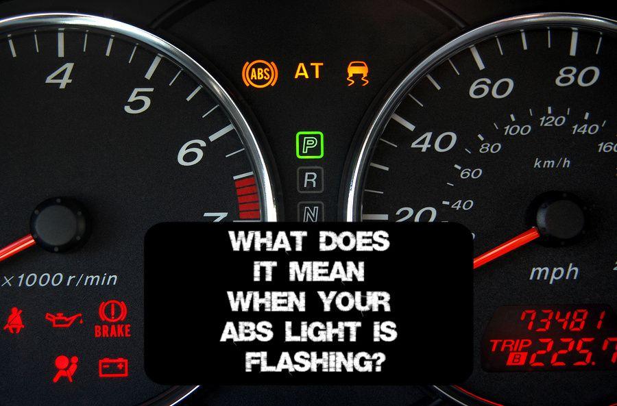
So, the dreaded ABS light has illuminated on your dashboard. Don't panic! While it signifies a problem, it doesn't necessarily mean your brakes are completely shot. This article will provide you with a comprehensive understanding of what that ABS light means, focusing on how the Anti-lock Braking System (ABS) works, common issues, and basic troubleshooting tips. Think of this as a deep dive into the ABS world, equipping you with the knowledge to diagnose and potentially fix the problem yourself. We'll approach this from the perspective of an experienced mechanic talking to a DIY enthusiast – clear, technical, but always practical.
Purpose of Understanding the ABS
Why bother understanding your ABS? The purpose extends beyond just silencing that annoying light. This knowledge empowers you to:
- Accurately Diagnose the Problem: A lit ABS light can indicate a range of issues, from a simple sensor malfunction to a more complex hydraulic problem. Understanding the system allows you to pinpoint the root cause.
- Perform Basic Repairs Yourself: Many ABS issues are relatively straightforward to fix with the right tools and knowledge. This can save you significant money compared to taking your vehicle to a professional mechanic.
- Make Informed Decisions: Even if you choose to take your car to a mechanic, understanding the problem helps you communicate effectively and avoid unnecessary repairs.
- Enhance Your Car Knowledge: Deepening your understanding of your vehicle's systems allows you to be a more proactive and confident car owner.
Key Specs and Main Parts of an ABS System
The Anti-lock Braking System is a sophisticated electro-hydraulic system designed to prevent wheel lockup during braking, maintaining steering control in emergency situations. Its main components are:
- Wheel Speed Sensors: Located at each wheel, these sensors constantly monitor the wheel's rotational speed. They are typically Hall-effect sensors or variable reluctance sensors. Hall-effect sensors use a magnetic field to detect changes in wheel speed, while variable reluctance sensors rely on the induction of a voltage within a coil.
- Hydraulic Control Unit (HCU): The "brains" of the ABS. It contains a series of valves, solenoids, and a pump that modulate brake pressure to individual wheels based on the information received from the wheel speed sensors. The HCU is essentially a small computer controlling hydraulic fluid under pressure.
- ABS Control Module (ECU): This electronic control unit receives signals from the wheel speed sensors and other inputs (like brake pedal position). It processes this data and sends commands to the HCU to regulate brake pressure.
- Brake Booster and Master Cylinder: These components provide the initial hydraulic pressure when you press the brake pedal. They are part of the regular braking system but work in conjunction with the ABS.
- Brake Lines: These lines carry the hydraulic fluid from the master cylinder and HCU to the brake calipers at each wheel.
Understanding ABS System Symbols and Wiring
An ABS system diagram can appear complex at first glance, but breaking down the symbols and wiring makes it easier to understand. Here's a basic overview:
- Lines: Solid lines typically represent hydraulic lines carrying brake fluid. Dashed lines usually represent electrical wiring.
- Colors: Wiring diagrams use different colors to identify specific wires and their functions. A legend accompanying the diagram will explain what each color represents (e.g., red for power, black for ground, yellow for signal).
- Icons: Common icons include:
- Resistors: A zig-zag line represents a resistor, which limits current flow.
- Capacitors: Two parallel lines represent a capacitor, which stores electrical energy.
- Diodes: A triangle pointing to a line represents a diode, which allows current to flow in one direction only.
- Solenoids: A coil symbol with a plunger represents a solenoid, an electromagnetically operated valve.
- Ground Symbol: A series of downward-pointing lines represents a ground connection.
- Connectors: Rectangular or circular symbols with numbers indicate electrical connectors. These connectors join different wiring harnesses together.
How the ABS System Works
The ABS system operates on a fairly straightforward principle: prevent wheel lockup. Here’s the process in detail:
- Normal Braking: Under normal braking conditions, the ABS system is essentially inactive. Brake pressure is applied directly from the master cylinder to the brake calipers.
- Impending Wheel Lockup: If a wheel begins to decelerate rapidly (indicating impending lockup), the wheel speed sensor sends a signal to the ABS control module (ECU).
- Pressure Modulation: The ECU then commands the hydraulic control unit (HCU) to modulate the brake pressure to that specific wheel. This is done by rapidly opening and closing solenoid valves within the HCU.
- Pressure Reduction, Holding, and Increase: The HCU can reduce pressure to the wheel that is about to lock up, hold the pressure constant, or even increase the pressure if the wheel regains traction. This rapid cycling of pressure happens several times per second.
- Maintaining Steering Control: By preventing wheel lockup, the ABS system allows the driver to maintain steering control during braking. This is because a rolling tire provides much better grip than a skidding tire.
- Cycling Action: You might feel a pulsating sensation in the brake pedal when the ABS is active. This is a normal byproduct of the rapid pressure modulation within the HCU.
Real-World Use: Basic Troubleshooting Tips
When your ABS light comes on, start with these basic troubleshooting steps:
- Visual Inspection: Check the wheel speed sensors for damage or loose connections. Inspect the brake lines for leaks.
- Scan for Codes: Use an OBD-II scanner to retrieve the diagnostic trouble codes (DTCs) stored in the ABS control module. These codes provide valuable clues about the source of the problem. Common codes relate to wheel speed sensor failures, hydraulic control unit malfunctions, and ECU issues.
- Wheel Speed Sensor Testing: You can test wheel speed sensors using a multimeter to check for resistance or voltage output. Consult your vehicle's service manual for specific testing procedures.
- Check Brake Fluid Level: Low brake fluid can sometimes trigger the ABS light. Top up the fluid if necessary and check for leaks in the system.
- Inspect ABS Fuses and Relays: Check the fuses and relays associated with the ABS system in your vehicle's fuse box. A blown fuse or faulty relay can prevent the ABS from functioning properly.
Example Scenario: If the scan tool shows a code indicating a faulty wheel speed sensor on the front left wheel, inspect the sensor and its wiring for damage. If the wiring is intact, you can test the sensor's resistance with a multimeter. If the sensor is faulty, replace it.
Safety Considerations
Working on the ABS system involves some safety risks, particularly when dealing with hydraulic components and electrical circuits:
- Brake Fluid: Brake fluid is corrosive and can damage painted surfaces. Wear eye protection and gloves when handling brake fluid. Dispose of used brake fluid properly.
- High Pressure: The hydraulic control unit operates under high pressure. Never disconnect brake lines while the system is pressurized. Depressurize the system according to your vehicle's service manual before disconnecting any lines.
- Electrical Components: Disconnect the negative battery terminal before working on any electrical components of the ABS system to prevent short circuits or electrical shock.
- Professional Help: If you're uncomfortable working on the hydraulic or electrical components of the ABS system, consult a qualified mechanic. Improper repairs can compromise the safety of your vehicle. Remember the brakes are important.
Important Note: After performing any repairs on the ABS system, it's crucial to bleed the brake system to remove any air that may have entered the lines. Follow the bleeding procedure outlined in your vehicle's service manual.
Hopefully, this helps clarify how to begin your ABS light analysis! You can get the full ABS System Diagram, along with a variety of other diagnostic tools and resources, by downloading the file here!