What Does The Abs Light Mean
Let's talk about that dreaded ABS light on your dashboard. It's more than just an annoying glow; it's your car's way of telling you something's amiss with a critical safety system. Understanding the ABS (Anti-lock Braking System) is crucial for any DIY mechanic or car enthusiast, whether you're diagnosing a problem, planning repairs, or just want to be a more informed owner. This article dives deep into the ABS system, helping you decipher what that light means and equipping you with the knowledge to tackle potential issues.
Purpose and Importance
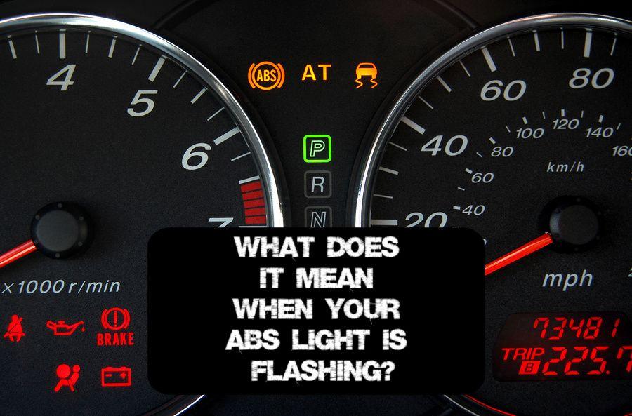
The Anti-lock Braking System prevents wheel lockup during hard braking, allowing you to maintain steering control. Wheel lockup can cause skidding, significantly increasing stopping distance and making it impossible to steer. The ABS modulates brake pressure to each wheel individually, preventing them from locking up and maximizing braking efficiency. When the ABS light illuminates, it indicates that the system has detected a fault and is likely disabled. This means your brakes will still function normally in most situations, but you'll lose the benefits of ABS in emergency braking situations. Diagnosing and repairing the ABS is paramount for road safety.
Key Specs and Main Parts of the ABS
A modern ABS system is a sophisticated network of sensors, actuators, and a dedicated control module. Here's a breakdown of the core components:
- Wheel Speed Sensors (WSS): These are typically inductive or Hall-effect sensors located at each wheel. They continuously monitor wheel speed and send data to the ABS control module. Any discrepancy in wheel speed readings can trigger the ABS light.
- ABS Control Module (ECU): The "brain" of the system. It receives data from the wheel speed sensors, calculates if a wheel is about to lock up, and commands the hydraulic unit to modulate brake pressure.
- Hydraulic Unit (HCU): This unit contains valves and a pump that regulate brake pressure to each wheel. When the ABS is activated, you'll feel a pulsation in the brake pedal – this is the HCU in action.
- Brake Booster and Master Cylinder: These are the standard hydraulic components that provide the base hydraulic pressure for braking. While not exclusively part of the ABS, they are essential to the overall braking system's function.
- Wiring Harness: Connects all the components, transmitting signals and power.
Key Specifications:
Sensor Type: Inductive or Hall-effect. Inductive sensors use a coil of wire to detect changes in magnetic field, while Hall-effect sensors use a semiconductor to detect magnetic fields. Each has pros and cons relating to precision, cost, and susceptibility to interference.
Operating Voltage: Typically 12V DC.
Communication Protocol: CAN bus (Controller Area Network) is the most common communication protocol used by the ABS module to communicate with other vehicle systems.
Understanding ABS System Symbols and Diagrams
Reading an ABS system diagram is crucial for diagnostics. Here's how to interpret common symbols and conventions:
- Lines: Solid lines usually represent electrical wires, while dashed lines might indicate communication buses (like CAN). Thicker lines often represent power wires, while thinner lines represent signal wires.
- Colors: Wire colors are standardized (though variations exist depending on the manufacturer). Understanding these color codes helps trace circuits and identify connections. For example, black is often ground, red is often a constant power source, and other colors indicate specific signal circuits.
- Icons: Standard electrical symbols represent various components, such as resistors, capacitors, diodes, and transistors. Learning to recognize these symbols is essential. Specifically, look for symbols representing the wheel speed sensors, the ABS control module, and the hydraulic unit.
- Ground Symbols: Indicate the points where the electrical circuit is grounded to the vehicle's chassis.
How the ABS Works: A Step-by-Step Explanation
Let's break down the ABS operation:
- Monitoring: Wheel speed sensors constantly transmit wheel speed data to the ABS control module.
- Analysis: The control module analyzes this data, comparing the speed of each wheel. If one wheel decelerates much faster than the others (indicating impending lockup), the system activates.
- Actuation: The control module signals the hydraulic unit to reduce brake pressure to the affected wheel. This is achieved through a series of valves that open and close rapidly.
- Pressure Modulation: The HCU modulates brake pressure, preventing the wheel from locking up. This modulation happens several times per second, creating the pulsating sensation in the brake pedal.
- Cycling: The system continuously monitors and adjusts brake pressure as needed, maintaining optimal braking performance and steering control.
Real-World Use: Basic ABS Troubleshooting
When the ABS light comes on, here are some basic troubleshooting steps you can take:
- Visual Inspection: Check the wheel speed sensors and wiring harnesses for damage or corrosion. Pay close attention to the sensor connections.
- OBD-II Scan: Use an OBD-II scanner to read the diagnostic trouble codes (DTCs). These codes will provide valuable information about the nature of the problem. Common codes relate to wheel speed sensor failures, hydraulic unit malfunctions, or communication errors.
- Sensor Testing: Use a multimeter to test the resistance and voltage of the wheel speed sensors. Compare the readings to the manufacturer's specifications.
- Wiring Continuity Test: Use a multimeter to check for continuity in the wiring harness between the wheel speed sensors and the ABS control module.
- Check Brake Fluid Level: Low brake fluid can sometimes trigger the ABS light.
Safety Precautions
Working on the braking system requires caution. Here are some key safety considerations:
- Depressurize the System: Before disconnecting any brake lines, depressurize the system by pumping the brake pedal several times with the engine off.
- Brake Fluid Handling: Brake fluid is corrosive. Wear gloves and eye protection when handling it. Clean up any spills immediately.
- Electrical Safety: Disconnect the negative battery terminal before working on the electrical components of the ABS system.
- High-Pressure Components: The hydraulic unit contains high-pressure fluid. Avoid disassembling it unless you have the proper tools and training. Incorrect disassembly can cause serious injury.
- Proper Torque: Always use a torque wrench and follow the manufacturer's specifications when tightening brake components.
Note: The ABS system is a complex system. If you are not comfortable working on it yourself, it is best to take your vehicle to a qualified mechanic.
I have a comprehensive ABS system diagram file that complements this article, providing visual aids and detailed information. This resource can greatly assist you in troubleshooting and understanding the intricacies of your vehicle's ABS. Feel free to reach out if you'd like a copy.