What Does The Electric Motor Do
Let's dive into the heart of what makes an electric motor tick. Whether you're considering an EV conversion, troubleshooting a hybrid vehicle, or just curious about how this increasingly prevalent technology works, understanding the electric motor is crucial. This article will provide a detailed breakdown, focusing on functionality, common components, and practical tips for dealing with these devices.
Why Understanding Electric Motor Diagrams Matters
Forget squinting at generic YouTube videos! Having access to detailed diagrams – and understanding them – is essential for informed decision-making when it comes to electric motors. From diagnosing unusual noises to attempting basic repairs (within your skill level, of course!), a solid grasp of these schematics allows you to:
- Troubleshoot effectively: Pinpoint faulty components instead of blindly replacing parts.
- Plan modifications: Understand the electrical system's limitations before attempting power upgrades.
- Communicate with professionals: Clearly articulate issues and understand the suggested solutions from mechanics.
- Stay safe: Identify high-voltage zones and avoid potentially lethal situations.
While we're not advocating for you to crack open an electric motor without proper training and equipment, knowing your way around a schematic empowers you to be a smarter and safer DIYer.
Key Specs and Main Parts of an Electric Motor
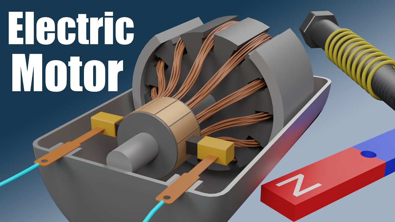
Electric motors come in various types (AC induction, permanent magnet synchronous, etc.), but they share fundamental components. Let's break down the key players:
- Stator: The stationary part of the motor. It contains coils of wire that, when energized, create a rotating magnetic field. Think of it as the foundation of the motor's power.
- Rotor: The rotating part of the motor. It interacts with the magnetic field created by the stator to produce torque. The type of rotor varies depending on the motor type.
- Windings: These are the coils of wire in the stator and sometimes the rotor. The way these windings are arranged and energized determines the motor's characteristics (speed, torque).
- Bearings: Support the rotor and allow it to rotate smoothly within the stator. Failing bearings are a common cause of motor noise and failure.
- Commutator (DC Motors): A set of bars or segments connected to the rotor windings. It works with brushes to switch the current direction in the windings, maintaining rotation. (Less common in modern EV motors, more prevalent in smaller DC applications)
- Brushes (DC Motors): Conduct electricity to the commutator. They wear down over time and need to be replaced. (Also less common in modern EV motors).
- Housing: The protective outer shell of the motor.
- Cooling System: Electric motors generate heat. This system (air or liquid cooled) prevents overheating, which can damage the motor.
- Resolver/Encoder: A sensor that provides feedback on the rotor's position and speed to the motor controller. This is crucial for precise motor control.
Key Specifications to Consider:
- Voltage (V): The operating voltage of the motor. High-voltage systems are common in EVs.
- Current (A): The amount of electrical current the motor draws.
- Power (kW or HP): The motor's power output.
- Torque (Nm or lb-ft): The twisting force the motor can produce.
- Speed (RPM): The rotational speed of the motor.
- Efficiency (%): The percentage of electrical energy converted into mechanical energy.
- Insulation Class: Indicates the motor's ability to withstand heat.
Understanding Symbols in Motor Diagrams
Motor diagrams utilize standardized symbols to represent various components. While specific symbols may vary slightly, here are some common ones:
- Windings: Typically shown as coiled lines. Three-phase windings are often represented with three separate coils.
- Resistors: Represented by a jagged line.
- Capacitors: Shown as two parallel lines.
- Diodes: A triangle pointing to a line.
- Transistors: Varied symbols depending on the type (BJT, MOSFET).
- Ground: Three horizontal lines, decreasing in length.
- Voltage Source: A circle with a + and - sign.
- Connections: Solid dots indicate a connection between wires, while crossing lines without a dot indicate no connection.
Lines:
- Solid lines: Represent electrical conductors (wires).
- Dashed lines: Often indicate mechanical connections or control signals.
- Colored lines: Used to distinguish different phases or voltage levels. For example, in a three-phase system, you might see red, blue, and black wires.
Always refer to the diagram's legend for specific symbol definitions.
How an Electric Motor Works
The fundamental principle behind electric motors is electromagnetism. Here's a simplified explanation:
- Current Creates a Magnetic Field: When an electric current flows through a wire, it creates a magnetic field around the wire.
- Stator Energized: The stator windings are energized with electricity, creating a rotating magnetic field. The frequency of the alternating current (AC) determines the speed of this rotating field.
- Rotor Interaction: The rotor, positioned within the stator's magnetic field, interacts with it. In an induction motor, the rotating magnetic field induces a current in the rotor windings, creating its own magnetic field. In a permanent magnet motor, the rotor contains permanent magnets that are attracted and repelled by the stator's field.
- Torque Production: The interaction between the stator and rotor magnetic fields produces a force that causes the rotor to rotate. This rotational force is torque.
- Motion: The rotating rotor drives the output shaft, providing mechanical power.
The motor controller precisely manages the current supplied to the stator windings, controlling the motor's speed and torque. Sophisticated algorithms are used to optimize performance and efficiency.
Real-World Use: Basic Troubleshooting Tips
While in-depth motor repair requires specialized knowledge, here are some basic troubleshooting steps you can take:
- Unusual Noises: Grinding or squealing sounds often indicate failing bearings. A buzzing sound could be a loose winding or insulation breakdown.
- Overheating: Check the cooling system for obstructions or malfunctions. Ensure the motor is not being overloaded.
- Lack of Power: Verify the power supply is adequate. Check for loose connections or damaged wiring. The motor controller may also be the culprit.
- Vibration: Could indicate unbalanced rotor or loose mounting.
Important: Before performing any troubleshooting, disconnect the power supply to the motor and follow proper lockout/tagout procedures.
Safety Considerations
Electric motors, particularly those used in EVs, can operate at very high voltages (hundreds of volts). These voltages are lethal.
- Never work on a motor while it's connected to a power source.
- Use insulated tools designed for high-voltage applications.
- Wear appropriate personal protective equipment (PPE), including insulated gloves and eye protection.
- Be aware of capacitor discharge: Capacitors can store a significant charge even after the power is disconnected. Properly discharge capacitors before working on the motor.
- If you are not comfortable working with high-voltage systems, consult a qualified technician.
Conclusion
Understanding the intricacies of electric motors, from their fundamental components to their operational principles, empowers you to engage more confidently with this technology. Whether you're diagnosing issues, planning modifications, or simply seeking to expand your knowledge, a solid grasp of motor diagrams and their underlying concepts is invaluable. Remember to prioritize safety and seek professional assistance when dealing with high-voltage systems.
We have a detailed electric motor diagram available for download. It includes labeled components, wiring schematics, and troubleshooting tips. You can use it to deepen your understanding and assist with your projects.