What Does The Engine Look Like
Alright, let's dive into what an engine really looks like. We're not talking about a glossy brochure picture; we're talking about a detailed diagram. Understanding this is crucial, whether you're planning a major engine rebuild, troubleshooting a persistent problem, or simply want to deepen your mechanical knowledge. This diagram will serve as a roadmap to your engine's inner workings, allowing for more informed decisions and safer practices in your automotive endeavors.
Purpose of an Engine Diagram
Why bother with an engine diagram? Well, think of it as the blueprint to your car's heart. It provides a visual representation of all the engine's components, their locations, and how they interact. This is incredibly useful for:
- Diagnosis: Pinpointing the source of a problem by identifying the components involved. For example, if you're experiencing misfires, the diagram helps you trace the ignition system, fuel injectors, and related sensors.
- Repair: Guiding you through the disassembly and reassembly process, ensuring everything goes back in its correct place. Ever struggled to remember where a hose goes? A diagram is your best friend.
- Modification: Planning upgrades and modifications, allowing you to visualize how new parts will integrate with existing systems. Thinking of installing a turbo? The diagram shows you where to tap into the oil and coolant lines.
- Learning: Comprehending the fundamental principles of engine operation and how different systems contribute to the overall performance. You'll understand the relationship between the crankshaft, pistons, and camshaft.
Key Specs and Main Parts
Let's break down the essential components depicted in a typical engine diagram. While specific layouts vary based on engine type (inline, V-shaped, rotary), certain core elements remain consistent:
Essential Specs (Example – Inline 4-Cylinder)
- Displacement: 2.0L (Total volume displaced by all pistons)
- Bore and Stroke: 86mm x 86mm (Diameter of the cylinder and distance the piston travels)
- Compression Ratio: 10:1 (Ratio of cylinder volume at bottom dead center to top dead center)
- Firing Order: 1-3-4-2 (Sequence in which cylinders ignite)
- Valve Configuration: DOHC (Dual Overhead Camshaft) 16-valve
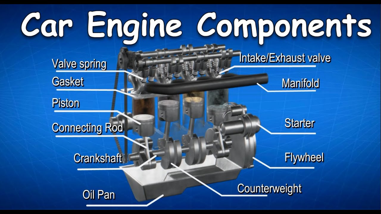
Main Parts
- Cylinder Block: The foundation of the engine, housing the cylinders. Typically made of cast iron or aluminum.
- Cylinder Head: Sits atop the cylinder block, containing the valves, camshaft(s), and combustion chambers. Also usually cast iron or aluminum.
- Pistons: Reciprocating components that move up and down within the cylinders, driven by combustion.
- Connecting Rods: Connect the pistons to the crankshaft, transmitting force.
- Crankshaft: Converts the linear motion of the pistons into rotational motion, which drives the transmission.
- Camshaft(s): Controls the opening and closing of the intake and exhaust valves.
- Valves (Intake & Exhaust): Regulate the flow of air and fuel into the cylinders and exhaust gases out.
- Intake Manifold: Distributes the air-fuel mixture to the cylinders.
- Exhaust Manifold: Collects exhaust gases from the cylinders.
- Oil Pan: Reservoir for engine oil.
- Water Pump: Circulates coolant through the engine to maintain temperature.
- Timing Belt/Chain: Connects the crankshaft and camshaft(s), synchronizing their rotation.
- Fuel Injectors: Spray fuel into the intake manifold or directly into the cylinders.
- Spark Plugs: Ignite the air-fuel mixture in the cylinders (gasoline engines).
Symbols and Conventions
Engine diagrams use a variety of symbols and conventions to represent different components and systems. Understanding these is crucial for accurate interpretation:
- Lines: Represent hoses, pipes, and electrical wires.
- Solid lines typically indicate fluid flow (oil, coolant, fuel).
- Dashed lines often represent vacuum lines or signal wires.
- Double lines can indicate a reinforced hose or pipe.
- Colors: May be used to differentiate systems. For example:
- Red might indicate high-pressure oil lines.
- Blue could represent coolant lines.
- Yellow might denote fuel lines.
- Icons: Represent specific components:
- A zigzag line often signifies a resistor.
- A circle with a "T" inside could represent a temperature sensor.
- Squares and rectangles generally depict control units or relays.
- Abbreviations: Diagrams are full of them! Common ones include:
- ECT: Engine Coolant Temperature
- MAF: Mass Airflow Sensor
- TPS: Throttle Position Sensor
- CKP: Crankshaft Position Sensor
- CMP: Camshaft Position Sensor
How It Works
An engine diagram doesn't just show you the parts; it hints at how they all work together. The four-stroke combustion cycle is at the heart of it all: Intake, Compression, Combustion (Power), and Exhaust. Let's see how the diagram helps visualize this:
- Intake: The diagram shows the intake valve opening, allowing the air-fuel mixture to enter the cylinder as the piston moves down. You can see the connection between the intake manifold, the intake valve, and the cylinder.
- Compression: Both intake and exhaust valves are closed as the piston moves up, compressing the mixture. The diagram illustrates the sealed combustion chamber.
- Combustion (Power): The spark plug ignites the compressed mixture, forcing the piston down. The diagram indicates the spark plug's position in the combustion chamber.
- Exhaust: The exhaust valve opens as the piston moves up, pushing the exhaust gases out of the cylinder. The diagram shows the connection between the exhaust valve, the exhaust manifold, and the catalytic converter.
The diagram also reveals the interconnectedness of systems. For example, the timing belt/chain synchronizes the crankshaft and camshaft(s), ensuring the valves open and close at the precise moments relative to the piston's position. The lubrication system, shown by oil lines and the oil pump, ensures all moving parts are properly lubricated, reducing friction and wear.
Real-World Use: Basic Troubleshooting Tips
Let's say you're experiencing a lack of power. Here's how a diagram can assist your troubleshooting:
- Check the basics: Is there sufficient fuel? Is the air filter clean? The diagram helps locate these components quickly.
- Look for vacuum leaks: Vacuum leaks can disrupt the air-fuel mixture. Trace the vacuum lines on the diagram, checking for cracks or loose connections.
- Inspect the ignition system: Are the spark plugs firing correctly? The diagram shows the location of the spark plugs, ignition coils, and related wiring.
- Examine the fuel system: Are the fuel injectors delivering fuel properly? The diagram displays the fuel rail, fuel injectors, and fuel pressure regulator.
By systematically examining these components based on the diagram, you can narrow down the potential causes of the problem and avoid unnecessary repairs.
Safety Considerations
Working on an engine involves inherent risks. The diagram can help you identify potentially hazardous areas:
- High-Voltage Components: The ignition system (spark plugs, ignition coils) carries high voltage. Always disconnect the battery before working on these components.
- High-Pressure Fuel Lines: Fuel lines can be under significant pressure. Relieve the pressure before disconnecting them.
- Hot Surfaces: The exhaust manifold and catalytic converter can get extremely hot. Allow the engine to cool down before working near them.
- Moving Parts: The crankshaft, camshaft(s), and timing belt/chain are all moving parts. Ensure the engine is off and the parking brake is engaged before working near them.
By being aware of these potential hazards, you can take the necessary precautions to ensure your safety.
Having access to a detailed engine diagram is an invaluable asset for any car owner or DIY mechanic. We've prepared a downloadable file containing a high-resolution, comprehensive engine diagram that you can use as a reference for your automotive projects. It includes exploded views, detailed component callouts, and troubleshooting guides. Take advantage of it and enhance your understanding and skillset!