What Does This Warning Light Mean
Okay, let's talk about that pesky warning light. Understanding these lights is crucial whether you're diving deep into your car's electrical system for modifications, performing routine maintenance, or just trying to diagnose a problem. This article will break down a typical automotive warning light diagram, focusing on its purpose, key components, how it works, and some real-world troubleshooting tips. We'll also emphasize safety, as electrical systems can be dangerous if handled improperly.
Purpose of a Warning Light Diagram
Why bother learning about warning light diagrams? Several reasons. First, they’re invaluable for diagnosis. When a light illuminates on your dash, it's triggering a specific circuit. The diagram shows you which components are involved in that circuit, allowing you to narrow down potential problem areas. Second, for those of you who like to tinker and modify your cars, understanding the electrical schematics is essential. Want to install aftermarket lights or audio equipment? The diagram shows you where to tap into power and ground safely and correctly. Finally, even for basic maintenance, knowing how the warning lights function helps you understand the health of your vehicle.
Key Specs and Main Parts
A typical warning light circuit is relatively simple. Here's a breakdown of the key parts:
- The Sensor: This is the component that detects a fault condition. Examples include oil pressure sensors, coolant temperature sensors, brake pad wear sensors, and ABS wheel speed sensors. These sensors often work by measuring a physical quantity (pressure, temperature, speed) and converting it into an electrical signal (voltage or resistance).
- The Wiring: Wiring is the nervous system of the car. It carries the signal from the sensor to the control unit and then to the warning light itself.
- The Control Unit (ECU/BCM): The Electronic Control Unit (ECU) or Body Control Module (BCM) is the brain. It receives signals from various sensors, processes that information, and determines whether a warning light should be activated.
- The Warning Light: This is the indicator on your dashboard that illuminates when a fault is detected. It's usually an LED or incandescent bulb.
- The Resistor (Sometimes): Some circuits use a resistor to limit current and protect the warning light bulb or LED.
- Power Source (Battery/Alternator): The entire system is powered by the car's battery, which is kept charged by the alternator.
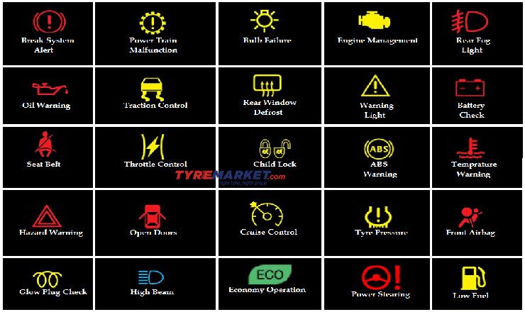
Symbols – Deciphering the Diagram
Understanding the symbols used in a warning light diagram is crucial. Here's a brief guide:
- Solid Lines: Represent wires. Thicker lines usually indicate wires that carry more current.
- Dashed Lines: Often indicate shielding or connections to ground.
- Colors: Wires are color-coded (e.g., red for power, black for ground). Color codes vary between manufacturers, so always consult the specific diagram for your vehicle. The color helps you identify the wire you are looking for in the harness.
- Icons: Each component has a specific icon. For example, a zigzag line represents a resistor, a circle with a 'T' inside often represents a temperature sensor, and a box with the letters 'ECU' represents the electronic control unit.
- Ground Symbol: Typically looks like a series of horizontal lines decreasing in size, connected to a wire. This indicates a connection to the vehicle's chassis, which serves as a common ground point.
- Numbers/Letters: These are often used to identify specific wires or pins on connectors. They are crucial for locating the correct wire in a wiring harness.
Line Types: Current Flow and Signals
Lines in a diagram don't just represent wires; they also represent the flow of electrical current or signals. A solid line typically means a direct electrical connection. A dashed line might represent a shielded wire, a signal path within a module, or even a CAN (Controller Area Network) bus line, which is used for communication between different ECUs in the vehicle.
How It Works: A Simple Example (Low Oil Pressure)
Let's use the low oil pressure warning light as an example. The oil pressure sensor is located on the engine block. It contains a diaphragm or other mechanism that is sensitive to oil pressure. When the oil pressure is low, the sensor sends a signal (usually a voltage drop or a change in resistance) to the ECU. The ECU then interprets this signal as a low oil pressure condition. In response, the ECU activates the low oil pressure warning light on the dashboard.
The circuit involves:
- Power from the battery (through a fuse).
- The oil pressure sensor.
- Wiring connecting the sensor to the ECU.
- The ECU.
- Wiring connecting the ECU to the warning light.
- The warning light (bulb or LED).
- A ground connection.
Real-World Use – Basic Troubleshooting Tips
So, the warning light is on. What do you do? First, consult your owner's manual! It will tell you what the light means and what immediate actions to take. Never ignore a warning light; it could indicate a serious problem. Here are a few basic troubleshooting steps:
- Visual Inspection: Check the wiring around the sensor. Look for damaged wires, loose connectors, or corrosion.
- OBD-II Scanner: Use an OBD-II scanner to read the diagnostic trouble code (DTC) stored by the ECU. This code can pinpoint the area of the problem. For example, a code like P0520 indicates a problem with the oil pressure sensor circuit.
- Sensor Testing: Use a multimeter to test the sensor. Check its resistance or voltage output. Compare your readings to the manufacturer's specifications.
- Wiring Continuity Test: Use a multimeter to check the continuity of the wiring between the sensor and the ECU. This verifies that the wires are not broken or shorted.
- ECU Testing: ECU failures are less common, but they can happen. Testing an ECU often requires specialized equipment and knowledge.
Example: You get a "Check Engine" light and the OBD-II code is P0118 (Engine Coolant Temperature Circuit High Input). Consult the wiring diagram for the coolant temperature sensor. Check the sensor itself for damage. Unplug the connector and inspect it for corrosion. Use a multimeter to check the resistance of the sensor, and compare it to the specified range for your car at the current temperature. Then, check the wiring from the sensor back to the ECU for continuity.
Safety – Respecting the Electrical System
Working on a car's electrical system can be dangerous if you don't take proper precautions. Here are some safety tips:
- Disconnect the Battery: Always disconnect the negative battery terminal before working on any electrical components. This prevents accidental shorts and electrical shocks.
- Use Proper Tools: Use insulated tools designed for automotive electrical work.
- Don't Work in Wet Conditions: Water and electricity don't mix.
- Be Careful with Airbags: Airbag systems are very sensitive and can be triggered accidentally if you tamper with them improperly. Consult a qualified technician before working on any airbag components.
- Understand Capacitors: Some components, like ECUs, contain capacitors that can store a charge even after the battery is disconnected. Discharge these capacitors before handling the component.
High-risk components: The airbag system and the high-voltage circuits in hybrid and electric vehicles are particularly dangerous. If you are not comfortable working on these systems, consult a qualified technician.
Understanding warning light diagrams empowers you to diagnose, maintain, and even modify your vehicle with greater confidence. Remember to always prioritize safety and consult the specific diagram for your car model. This knowledge will save you time, money, and potential headaches down the road. We have a comprehensive file containing various warning light diagrams and detailed explanations. Contact us, and we will gladly provide you with a download link. Good luck!