What Is A Abs Light On A Car
The Anti-lock Braking System (ABS) light illuminating on your dashboard is more than just an annoyance; it's a critical indicator that a key safety feature in your vehicle is potentially compromised. As an experienced DIYer, understanding the ABS system, its components, and how to diagnose problems is crucial for maintaining your vehicle's safety and performance. This article will delve into the intricacies of the ABS, empowering you to troubleshoot issues and potentially save on expensive mechanic bills. We also have detailed diagrams available for download that will further aid your understanding and repair efforts.
Purpose of Understanding the ABS Light
Knowing what triggers the ABS light is essential for several reasons:
- Safety: The ABS is a vital safety system, preventing wheel lock-up during hard braking, which allows you to maintain steering control. A malfunctioning ABS can significantly increase stopping distances and the risk of accidents.
- Preventing Further Damage: Addressing the issue promptly can prevent more extensive and costly repairs. A seemingly minor sensor problem can, if ignored, lead to damage to the ABS module itself.
- Cost Savings: Diagnosing and, in some cases, repairing ABS issues yourself can save you a considerable amount of money compared to professional repairs.
- Learning and Modification: Understanding the ABS is especially important if you are planning to modify or upgrade your braking system. You need to be aware how modifications could affect the ABS functionality.
Key Specs and Main Parts of the ABS
The ABS is a sophisticated system composed of several key components working in concert. Understanding these parts is crucial for effective troubleshooting:
Wheel Speed Sensors (WSS)
Also known as ABS sensors, these are typically located at each wheel hub. They monitor the rotational speed of each wheel and send this data to the ABS control module. These sensors can be either inductive or Hall-effect sensors. Inductive sensors generate an AC voltage signal based on the wheel's rotation, while Hall-effect sensors use a magnetic field to generate a digital signal. A common specification is the voltage output range or the frequency of the signal at a given wheel speed.
ABS Control Module (ECU)
The brain of the ABS, the ECU (Electronic Control Unit) receives information from the wheel speed sensors. It continuously monitors this data and, when it detects a wheel is about to lock up during braking, it activates the hydraulic modulator. Specifications include processing speed, memory capacity, and the number of input/output channels. It's important to note that the ECU often has fault codes to help diagnosis.
Hydraulic Modulator (HCU)
This component contains a series of solenoid valves that control the brake pressure to each wheel. When the ECU detects wheel lock-up, it signals the modulator to rapidly release and reapply brake pressure, preventing the wheel from locking. The modulator uses solenoids, which are electromechanical devices that operate the valves. The speed at which these valves cycle (measured in Hertz, Hz) is a crucial performance parameter. Specifications include operating pressure range and the cycling frequency.
Brake Booster and Master Cylinder
While not strictly part of the ABS, the brake booster and master cylinder provide the hydraulic pressure that the ABS modulates. The booster amplifies the force you apply to the brake pedal, and the master cylinder converts this force into hydraulic pressure. Specifications to keep in mind when upgrading or repairing these include the master cylinder bore size (which affects brake pedal feel and braking power) and the booster's amplification ratio.
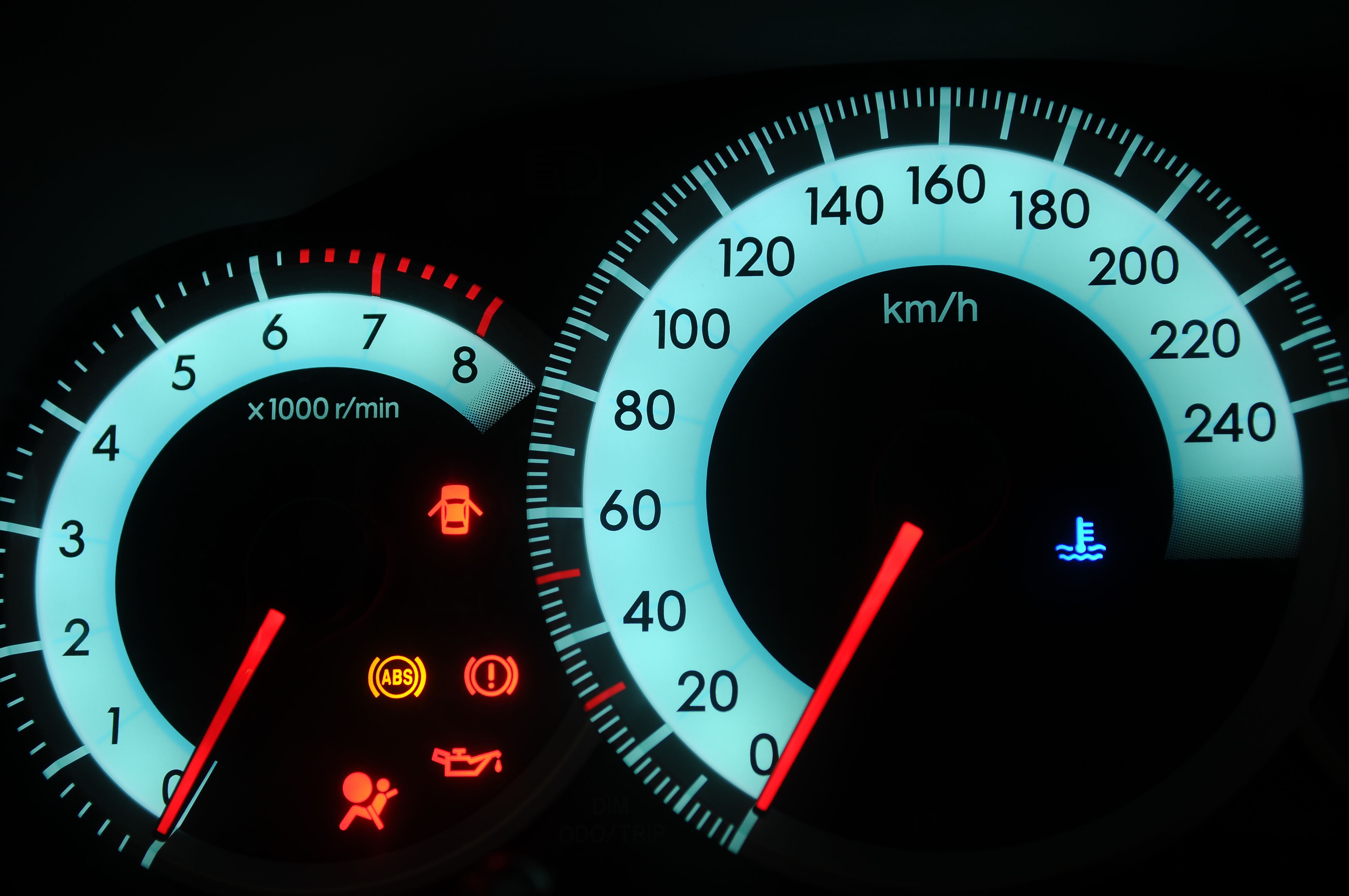
ABS Warning Light
This indicator on your dashboard illuminates when the ABS control module detects a fault within the system. It's crucial to pay attention to this light and diagnose the problem promptly.
Symbols and Wiring Diagram Conventions
Understanding the symbols used in ABS wiring diagrams is key to diagnosing electrical issues. Here's a breakdown of common conventions:
- Solid Lines: Represent wires or electrical conductors. Thicker lines usually indicate higher current-carrying capacity.
- Dashed Lines: May indicate shielded wires, or connections within a component, or communication buses like CAN (Controller Area Network).
- Color Coding: Wires are often color-coded to identify their function. Common colors include red (power), black (ground), and various other colors for signals. Consult your vehicle's specific wiring diagram for the color code legend.
- Connectors: Represented by circles or rectangles, with numbers indicating pin assignments.
- Ground Symbols: Usually depicted as a series of horizontal lines decreasing in size, indicating a connection to the vehicle's chassis ground.
- Component Symbols: Each component (sensor, module, solenoid) has a specific symbol. Refer to a legend within the diagram.
How ABS Works
The ABS works by constantly monitoring the speed of each wheel. When you brake hard, the system detects if one or more wheels are slowing down significantly faster than the others, indicating an impending lock-up. If this happens, the ECU signals the hydraulic modulator to rapidly release and reapply brake pressure to the affected wheel. This process, called threshold braking, happens many times per second, preventing the wheel from locking up and allowing you to maintain steering control.
Important Concept: The ABS doesn't simply release the brakes entirely; it modulates the pressure, allowing the wheel to slow down without locking. This is crucial for maintaining optimal braking force and steering control.
Real-World Use: Basic Troubleshooting Tips
When the ABS light comes on, here are some initial troubleshooting steps you can take:
- Check the Brake Fluid Level: Low brake fluid can sometimes trigger the ABS light.
- Inspect Wheel Speed Sensors: Check for damage to the sensors or their wiring harnesses. Look for loose connections, frayed wires, or physical damage. Use a multimeter to test the sensor's resistance according to your vehicle's service manual.
- Scan for Diagnostic Trouble Codes (DTCs): Use an OBD-II scanner to retrieve ABS-specific codes. These codes can pinpoint the source of the problem. Common codes relate to wheel speed sensors, the ABS module, or hydraulic modulator. For example, code C0035 often indicates a problem with the front right wheel speed sensor.
- Check the ABS Fuses: Blown fuses can disable the ABS. Consult your owner's manual or wiring diagram to locate the ABS fuses and check their condition.
- Inspect the ABS Module Connector: Ensure the connector is securely attached to the ABS module and that the pins are clean and free from corrosion.
If you find a problem with a wheel speed sensor, you can often replace it yourself. After replacing a sensor, clear the DTCs and perform a test drive to ensure the ABS light remains off. For more complex issues, such as a faulty ABS module, it's often best to consult a professional mechanic.
Safety Considerations
Working on the ABS system involves handling hydraulic components and electrical connections. Here are some important safety precautions:
- Disconnect the Battery: Always disconnect the negative battery terminal before working on any electrical components in the ABS system to prevent short circuits and electrical shock.
- Brake Fluid: Brake fluid is corrosive and can damage painted surfaces. Wear eye protection and gloves when handling brake fluid. If brake fluid comes into contact with your skin or eyes, flush immediately with water.
- Hydraulic Pressure: Be aware that the brake system can retain significant hydraulic pressure even after the engine is off. When disconnecting brake lines, release the pressure carefully to avoid injury.
- ABS Module: The ABS module contains sensitive electronic components. Handle it with care and avoid static electricity.
Caution: The Hydraulic Modulator holds high pressure and must be treated with respect! If not properly depressurized before removal lines can spray brake fluid at high pressure and cause eye or skin irritation.
Conclusion
Understanding the ABS system is crucial for maintaining your vehicle's safety and performance. By familiarizing yourself with the system's components, wiring diagrams, and troubleshooting techniques, you can diagnose and potentially repair ABS issues yourself, saving time and money. Remember to always prioritize safety when working on your vehicle's braking system. And, don't forget, we have comprehensive diagrams available for download that can provide even greater detail and assistance with your repairs.