What Is A Cvt Auto Gearbox
Alright, let's dive into the fascinating world of Continuously Variable Transmissions, or CVTs. Think of this as your deep-dive resource, designed to help you understand what's under the hood – or rather, inside the gearbox – of many modern vehicles.
Purpose of Understanding CVT Diagrams and Operation
Why bother learning about CVTs? Simple. Whether you're planning on basic maintenance, diagnosing a strange noise, or even contemplating performance modifications (proceed with caution!), understanding the internal workings of your car's transmission is crucial. Diagrams, technical specifications, and operational knowledge provide a framework for:
- Accurate Diagnosis: Identify the root cause of transmission issues, saving time and money.
- Informed Maintenance: Understand recommended service intervals and fluid specifications to prolong the life of your CVT.
- Safe Modifications: If you're considering performance upgrades, knowing the CVT's limitations is essential to avoid catastrophic failures.
- General Car Knowledge: A deeper understanding of how your vehicle works empowers you as a car owner and potentially saves you big repair bills.
Key Specs and Main Parts
A CVT isn't your traditional automatic transmission with fixed gear ratios. Instead, it uses a system of belts and pulleys to achieve a virtually infinite range of gear ratios. Here are the key components:
- Input Shaft: Connects the engine to the CVT.
- Primary (Driving) Pulley: Connected to the input shaft, this pulley's diameter changes to vary the gear ratio. Also known as the *drive pulley*.
- Secondary (Driven) Pulley: Connected to the output shaft, driving the wheels. Its diameter also changes in coordination with the primary pulley. Also known as the *driven pulley*.
- Belt (Usually a Steel V-Belt): A robust belt that connects the two pulleys and transmits power. The *steel V-belt* is constructed of many interlocking steel segments held together by steel bands and is designed to withstand tremendous force.
- Hydraulic Control System: Precisely regulates the pressure applied to the pulleys, controlling their diameter and, therefore, the gear ratio. This often includes a valve body, solenoids, and various sensors.
- Transmission Control Unit (TCU): The "brain" of the CVT, receiving input from various sensors and controlling the hydraulic system to achieve the desired gear ratio.
- Forward/Reverse Gear Set: Allows the vehicle to move in both directions.
- Torque Converter (Sometimes): Some CVTs, especially in higher-horsepower applications, still use a torque converter for smoother launch and torque multiplication at low speeds. Other designs may use a fluid coupling or a wet clutch pack.
Key Specs to Consider:
- Torque Capacity: The maximum amount of torque the CVT can handle without damage.
- Ratio Spread: The difference between the lowest and highest gear ratios the CVT can achieve. A wider ratio spread generally improves fuel economy and acceleration.
- Fluid Type: Using the correct CVT fluid is critical. Different CVTs require different fluid formulations. Using the wrong fluid can cause severe damage. Consult your owner's manual.
Understanding CVT Diagram Symbols
Technical diagrams use specific symbols to represent components. Here's a general guide:
- Solid Lines: Represent mechanical connections, like shafts and linkages.
- Dashed Lines: Indicate hydraulic lines or control signals.
- Circles: Often represent rotating components like pulleys, gears, and clutches.
- Rectangles: May represent sensors, solenoids, or electronic control units.
- Arrows: Show the direction of fluid flow or movement.
- Color Coding: Often (but not always) indicates different pressure levels in hydraulic systems or different types of signals in electrical circuits. Refer to the diagram's legend.
Pay close attention to the diagram's legend or key. It will define the specific meaning of each symbol used in that particular diagram. Don't assume a symbol means the same thing across all diagrams.
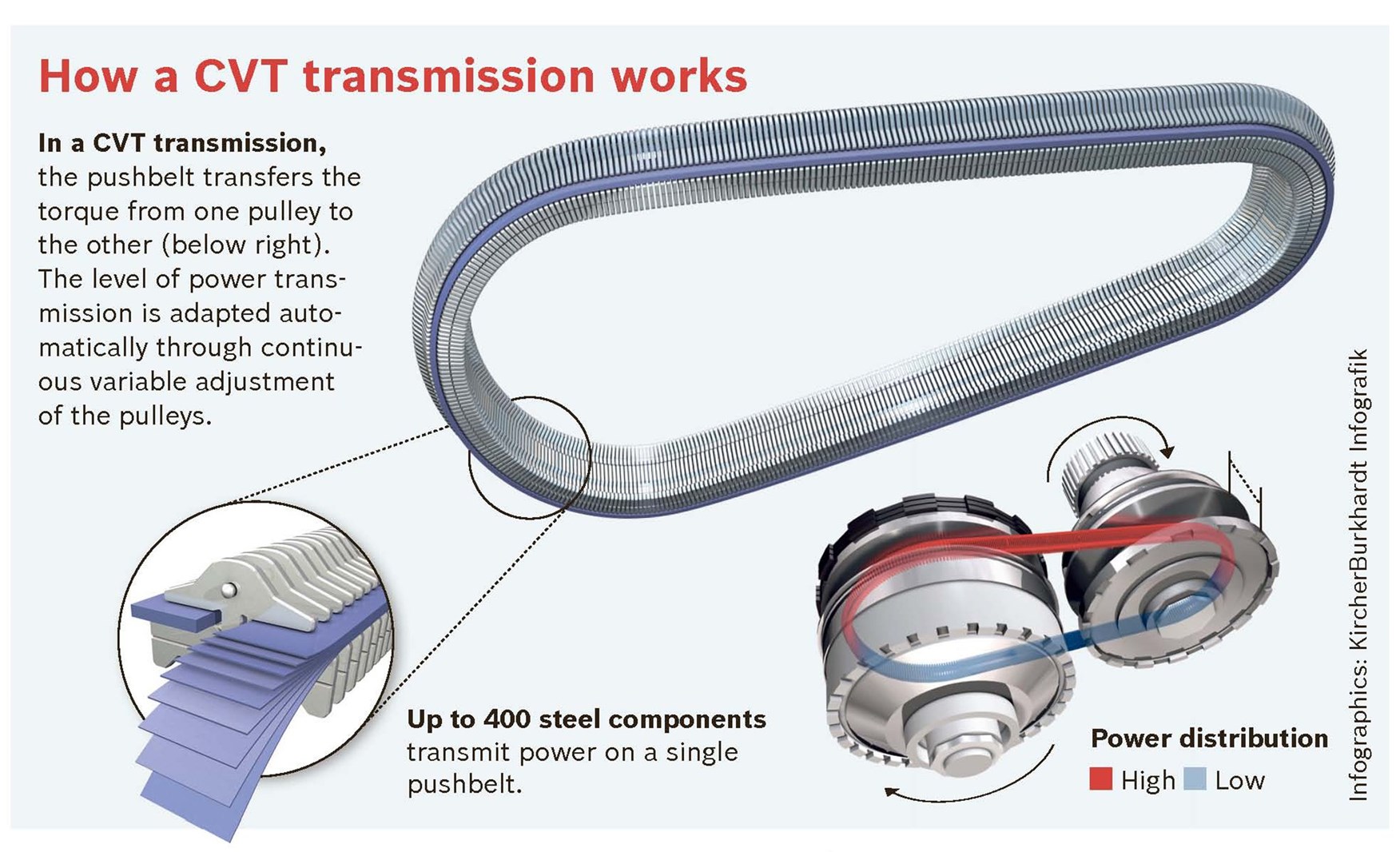
How a CVT Works
The magic of a CVT lies in its ability to continuously adjust the gear ratio. Here's the basic principle:
- The engine's power is transmitted to the primary pulley.
- The TCU monitors various factors, such as engine speed, vehicle speed, and throttle position.
- Based on this information, the TCU signals the hydraulic control system to adjust the diameter of the primary and secondary pulleys.
- The hydraulic system uses fluid pressure to move the pulley halves closer together or further apart. When the pulley halves move closer together, the belt rides higher on the pulley, effectively increasing the pulley's diameter. When the pulley halves move apart, the belt rides lower, decreasing the effective diameter.
- As one pulley's diameter increases, the other pulley's diameter decreases proportionally, maintaining constant belt tension.
- By continuously adjusting the pulley diameters, the CVT can achieve an infinite number of gear ratios within its specified range. This allows the engine to operate at its most efficient speed for any given driving condition.
Imagine riding a bicycle with continuously variable gears. You can seamlessly adjust the gear ratio to maintain a comfortable pedaling cadence, regardless of the terrain. That's the basic idea behind a CVT, but implemented with pulleys, belts, and sophisticated electronic control.
Real-World Use and Basic Troubleshooting
Here are a few common CVT issues and basic troubleshooting tips:
- Slipping or Jerking: Often caused by low or contaminated CVT fluid. Check the fluid level and condition. If the fluid is dark or smells burnt, it needs to be changed. Always use the correct CVT fluid specified by the manufacturer.
- Whining Noise: Could indicate worn pulley bearings or a damaged belt. Requires professional diagnosis and repair.
- Delayed Engagement: May be due to low fluid pressure or a faulty solenoid in the hydraulic control system.
- "Check Engine" Light: A fault code related to the CVT could indicate a sensor malfunction, a problem with the TCU, or a mechanical issue within the transmission. Have the code read by a qualified technician.
Important Note: CVT repairs can be complex and often require specialized tools and knowledge. If you're not comfortable working on transmissions, it's best to leave it to a professional.
Safety Considerations
Working on a CVT involves several safety hazards:
- High Pressure Hydraulic System: The hydraulic control system operates at high pressures. Incorrectly disconnecting lines can result in serious injury from high-pressure fluid injection.
- Heavy Components: CVTs are heavy and awkward to handle. Use proper lifting equipment and techniques to avoid injury.
- Rotating Parts: Keep hands and clothing away from rotating parts when the engine is running.
- Hot Surfaces: The transmission can get very hot during operation. Allow it to cool down before working on it.
- Proper Support: Always use jack stands to support the vehicle when working underneath it. Never rely solely on a jack.
The steel V-belt operates under tremendous tension. If a CVT fails catastrophically, there is a risk of the belt breaking and causing damage. It is essential to follow all safety precautions when working on or around a CVT.
I've got a detailed diagram of a common CVT assembly, broken down by its key components. You can download that file for a closer look. Good luck, and remember to be safe!