What Is A Map Light In A Car
Alright, let's dive into the inner workings of one of those often-overlooked, yet essential, components in your car: the map light. Whether you're tackling a wiring project, upgrading to LEDs, or simply trying to diagnose why that little beam of light refuses to cooperate, understanding how a map light works is crucial. This article provides a detailed overview of map lights, covering their purpose, key components, operation, and troubleshooting. Plus, we've got the wiring diagram for you – which you can download at the end of the article.
Purpose and Importance
Why bother understanding a simple map light? Well, it's more than just a convenience feature. Map lights serve several important purposes:
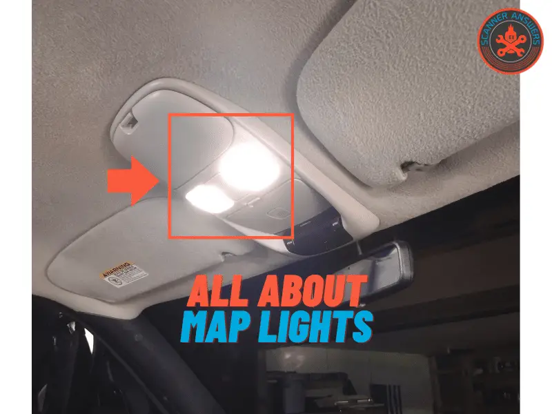
- Illumination: Primarily, they provide focused light for reading maps (yes, some people still use them!), finding items in the dark, or illuminating the cabin for other tasks without distracting the driver.
- Convenience: They offer independent control, allowing the passenger to have light without affecting the driver's vision, unlike the main dome light.
- Troubleshooting Skills: Understanding their circuit is a gateway to grasping more complex automotive electrical systems.
Knowing the basics of the map light circuit helps with general electrical troubleshooting. After all, electrical issues tend to cascade, and a faulty map light could indicate a larger problem with the car's electrical system.
Key Specs and Main Parts
The core components of a typical map light system are relatively straightforward:
- Light Bulb/LED: The light source itself. Older vehicles typically used incandescent bulbs (e.g., festoon or wedge-base bulbs), while newer models increasingly use LEDs. LEDs offer greater efficiency, longer lifespan, and lower heat output.
- Switch: The on/off switch that controls the flow of electricity to the bulb. Often, map lights have two switches: one for each light, allowing individual control. Some also include a "door-activated" switch, allowing the light to turn on when the door is opened.
- Housing/Assembly: The physical enclosure that holds the bulb, switch, and wiring. This may include a lens or reflector to focus or diffuse the light.
- Wiring: The electrical wires that connect the light to the car's electrical system. This includes the power wire (typically +12V), the ground wire, and any wires connecting to the door switch circuit.
- Fuse: An often-overlooked but crucial component. The fuse protects the circuit from overcurrent, preventing damage to the wiring and other components. The map light usually shares a fuse with other interior lights.
- Voltage Regulator (Sometimes): In vehicles with more sophisticated electrical systems or LED map lights, a voltage regulator may be included to ensure a stable voltage supply to the light. This is particularly important for LEDs, which are sensitive to voltage fluctuations.
Key Specifications:
- Voltage: Typically 12V DC (Direct Current).
- Wattage: Varies depending on the bulb type. Incandescent bulbs usually range from 5W to 10W, while LEDs are typically much lower, around 1W to 3W.
- Fuse Rating: Usually 5A to 10A, shared with other interior lights. Consult your vehicle's owner's manual for the correct fuse rating.
Understanding the Wiring Diagram
The wiring diagram is your roadmap for understanding the map light circuit. Here's a breakdown of the common symbols and conventions:
- Solid Lines: Represent wires. The thickness of the line may indicate the wire gauge (thicker lines = thicker wires).
- Dotted Lines: May represent a connection to ground (chassis ground) or a shielded cable.
- Colors: Wires are often color-coded to help identify them. Common colors include red (power), black (ground), and other colors for specific circuits (e.g., blue for door switch).
- Symbols for Components:
- Bulb: Typically represented by a circle with a filament inside.
- Switch: Represented by a line that can be open (off) or closed (on).
- Fuse: Represented by a zig-zag line inside a rectangle.
- Ground: Represented by a series of downward-pointing lines or a triangle.
- Voltage Regulator: Represented by a rectangle with input and output terminals.
- Numbers and Letters: These identify specific wires, terminals, or connectors. They are often used to cross-reference between different parts of the diagram.
A typical map light circuit will show the +12V power source connected to a fuse, then to the switch, and finally to the light bulb. The other side of the bulb is connected to ground, completing the circuit. The door switch circuit will typically connect to the ground side of the bulb, allowing the light to turn on when the door is opened and completing the ground connection. Look for wire labels like "IGN" (ignition), "GND" (ground), and "LMP" (lamp). Also look for labels specifying amperage and voltage.
How It Works
The principle behind a map light is simple: completing an electrical circuit allows current to flow, illuminating the bulb. Here's a step-by-step breakdown:
- Power Source: The car's battery provides the +12V DC power.
- Fuse Protection: The fuse protects the circuit from overcurrent. If there's a short circuit, the fuse will blow, breaking the circuit and preventing damage.
- Switch Control: When the map light switch is turned on, it closes the circuit, allowing current to flow from the power source to the light bulb.
- Illumination: The current flows through the filament (in an incandescent bulb) or the LED, causing it to heat up and emit light.
- Ground Connection: The current then flows from the bulb to ground, completing the circuit and allowing the process to continue.
- Door Switch (Optional): If the map light has a door switch, it provides an alternate ground path. When the door is opened, the door switch closes, completing the ground connection and turning on the light, even if the manual switch is off.
Real-World Use: Basic Troubleshooting
If your map light isn't working, here's a systematic approach to troubleshooting:
- Check the Bulb: This is the easiest first step. Replace the bulb with a known good one. If it still doesn't work, proceed to the next step.
- Check the Fuse: Locate the fuse for the interior lights (consult your owner's manual). If the fuse is blown, replace it with a fuse of the correct amperage. If the fuse blows again immediately, there's likely a short circuit in the wiring.
- Check the Switch: Use a multimeter to check if the switch is working correctly. With the switch on, you should see continuity between the terminals. If there's no continuity, the switch is faulty and needs to be replaced.
- Check the Wiring: Use a multimeter to check for voltage at the bulb socket. With the switch on, you should see approximately 12V. If there's no voltage, there's a break in the wiring between the fuse and the bulb socket. Also, check for a good ground connection.
- Inspect the Connectors: Check the connectors for corrosion or loose connections. Clean or replace the connectors as needed.
- Door Switch Malfunction: Disconnect the door switch wire from the map light. If the light starts working with the manual switch, the door switch is likely faulty or misadjusted.
Common Issues:
- Blown Fuse: Often caused by a short circuit in the wiring or a faulty bulb.
- Faulty Bulb: Incandescent bulbs have a limited lifespan and can burn out.
- Corroded Connections: Corrosion can prevent current from flowing.
- Broken Wiring: Wires can become damaged due to age, vibration, or physical damage.
- Faulty Switch: Switches can wear out over time.
Safety Considerations
Working with automotive electrical systems requires caution:
- Disconnect the Battery: Before working on any electrical circuit, disconnect the negative terminal of the battery to prevent accidental short circuits.
- Use a Multimeter: A multimeter is essential for diagnosing electrical problems. Learn how to use it to check for voltage, continuity, and resistance.
- Avoid Working in Wet Conditions: Water can conduct electricity and increase the risk of electric shock.
- Protect Your Eyes: Wear safety glasses to protect your eyes from sparks or debris.
- Be Careful with Wiring: Avoid pulling or tugging on wires, as this can damage them.
- Understand Fuses: Never replace a fuse with one of a higher amperage rating. This can overload the circuit and cause a fire.
Specifically, the power wire (+) is the riskiest. Shorting this to the chassis ground can create sparks and potentially damage your vehicle's electrical system. Always disconnect the negative battery terminal before working with any automotive wiring.
We hope this guide has provided you with a solid understanding of map lights and their operation. By understanding the components, wiring, and troubleshooting techniques, you'll be well-equipped to diagnose and repair any issues that may arise. Download the detailed map light wiring diagram below for a visual aid to your repairs.
Download the Map Light Wiring Diagram: [Link to Download - Placeholder]