What Is A Master Warning Light
Alright, let's talk about the Master Warning Light, often referred to as the "idiot light" but technically a sophisticated alert system designed to prevent catastrophic failures. If you're an experienced DIYer, modder, or just a mechanically inclined car owner, understanding this system is crucial. It's not just about silencing that annoying light; it's about understanding the health of your vehicle and avoiding costly repairs down the line.
Purpose
The Master Warning Light's primary purpose is to alert the driver to a critical system malfunction that requires immediate attention. It acts as a centralized warning hub, triggered by various sensors and modules throughout the vehicle. Think of it as the "check engine light" on steroids, indicating a problem severe enough to warrant immediate investigation. Understanding this light and its triggers is essential for:
- Preventative Maintenance: Catching problems early before they lead to major breakdowns.
- Accurate Diagnosis: Quickly identifying the system at fault, saving time and money on troubleshooting.
- Safety: Avoiding potentially dangerous situations caused by malfunctioning systems.
- Performance Enhancement: Monitoring critical systems to ensure optimal performance, especially useful for modified vehicles.
Key Specs and Main Parts
The Master Warning Light system, while seemingly simple, relies on a network of interconnected components. Here's a breakdown of the key players:
Sensors
These are the eyes and ears of the system. They monitor various parameters such as:
- Oil Pressure Sensor: Measures engine oil pressure.
- Coolant Temperature Sensor: Monitors engine coolant temperature.
- Brake Fluid Level Sensor: Detects low brake fluid levels.
- Charging System Sensor: Monitors alternator output and battery voltage.
- Engine Management System (EMS): Monitors a wide range of engine parameters (e.g., fuel trim, misfires) and communicates with the warning system.
These sensors typically output an analog voltage or a digital signal to the control module.
Control Module
This is the brain of the system. It receives signals from the sensors, interprets them, and determines if a warning light activation is necessary. The module typically contains:
- Microcontroller: Processes sensor data and executes logic.
- Memory: Stores fault codes and system parameters.
- Output Drivers: Control the activation of the Master Warning Light and other warning indicators.
- Communication Interface: Allows the module to communicate with other vehicle systems (e.g., CAN bus).
The Master Warning Light Indicator
This is the light itself, usually located on the instrument cluster. It's often a bright red or amber color and may be accompanied by an audible alarm. The indicator illuminates when the control module detects a critical fault.
Wiring Harness
This is the nervous system of the system, connecting all the components together. Wiring diagrams are crucial for troubleshooting.
Symbols
Understanding the symbols used in wiring diagrams is essential for tracing circuits and diagnosing faults. Here are some common symbols you'll encounter:
- Lines: Represent wires. The thickness of the line may indicate the wire gauge (current carrying capacity). Dashed lines often indicate shielded wires.
- Colors: Indicate the wire color (e.g., Red, Black, Blue). Color codes are standardized, but variations may exist between manufacturers.
- Ground Symbol: Indicates a connection to the vehicle's chassis ground.
- Battery Symbol: Indicates a connection to the vehicle's battery.
- Resistor Symbol: Indicates a resistor in the circuit.
- Capacitor Symbol: Indicates a capacitor in the circuit.
- Diode Symbol: Indicates a diode in the circuit.
- Sensor Symbols: Vary depending on the type of sensor (e.g., pressure sensor, temperature sensor).
- Module Symbols: Typically represented as rectangular boxes with pin numbers indicating the connector terminals.
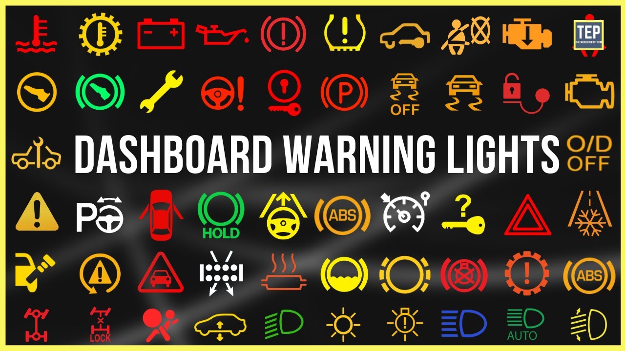
The icons displayed on the Master Warning Light itself also have specific meanings. Common icons include:
- Oil Can: Indicates low oil pressure.
- Thermometer: Indicates high coolant temperature.
- Brake Symbol: Indicates low brake fluid or a problem with the braking system.
- Battery Symbol: Indicates a charging system fault.
- Exclamation Point (!): Often a generic warning symbol that requires further investigation.
How It Works
The system operates on a simple principle: sensors monitor critical parameters, and the control module compares these values to pre-programmed thresholds. If a parameter falls outside the acceptable range, the module activates the Master Warning Light.
For example, if the oil pressure sensor detects that the engine oil pressure is below the minimum threshold, it sends a signal to the control module. The module then activates the Master Warning Light and may also store a diagnostic trouble code (DTC) in its memory. This DTC can be retrieved using a scan tool, providing valuable information for troubleshooting.
The control module uses a combination of analog and digital signals to make its decisions. Analog signals provide a continuous range of values, while digital signals are either on or off. The module also uses logic gates (e.g., AND, OR, NOT) to combine signals and create more complex decision-making processes.
Real-World Use – Basic Troubleshooting Tips
When the Master Warning Light illuminates, the first step is to safely pull over and assess the situation. Don't ignore it! Continuing to drive with a critical fault can lead to serious engine damage or even a breakdown.
- Check the Obvious: Check your oil level, coolant level, and brake fluid level. A simple fix like adding fluid could resolve the issue.
- Listen for Unusual Noises: Pay attention to any unusual noises coming from the engine, brakes, or other systems.
- Use a Scan Tool: If you have a scan tool, retrieve the DTCs from the control module. This will provide valuable clues about the source of the problem.
- Consult a Wiring Diagram: Use a wiring diagram to trace the circuit associated with the DTC. This will help you identify potential problems such as short circuits, open circuits, or faulty sensors.
- Test the Sensors: Use a multimeter to test the sensors and verify that they are functioning correctly. Check the sensor's resistance, voltage output, and signal integrity.
- Check the Wiring: Inspect the wiring harness for any signs of damage, such as frayed wires, corroded connectors, or loose connections.
Example: The Master Warning Light comes on, and the scan tool retrieves a DTC indicating low oil pressure. Using a wiring diagram, you can trace the circuit from the oil pressure sensor to the control module. You can then use a multimeter to test the sensor and verify that it is producing the correct voltage signal. If the sensor is faulty, replacing it may resolve the issue. If the sensor is good, the problem may be a wiring issue or a faulty oil pump.
Safety – Highlight Risky Components
Working on automotive electrical systems can be dangerous if proper precautions are not taken. Here are some key safety considerations:
- Disconnect the Battery: Always disconnect the negative battery cable before working on any electrical components. This will prevent accidental short circuits.
- Work in a Well-Ventilated Area: When working with gasoline or other flammable liquids, work in a well-ventilated area to avoid the risk of fire or explosion.
- Wear Safety Glasses: Wear safety glasses to protect your eyes from flying debris or accidental splashes.
- Use Proper Tools: Use properly insulated tools to avoid electric shock.
- Be Aware of High-Voltage Components: Be especially careful when working on components such as the ignition system or the charging system, as these systems can produce high voltages.
- Consult the Service Manual: Always consult the service manual for your vehicle before attempting any repairs. The service manual will provide detailed instructions and safety precautions.
Specific components that require extra caution include:
- Fuel System Components: Handle fuel lines and fuel injectors with extreme care to avoid fuel leaks and potential fire hazards.
- Airbag System Components: The airbag system contains explosives and should only be serviced by qualified technicians. Accidental deployment of an airbag can cause serious injury.
- High-Voltage Hybrid System Components: Hybrid vehicles contain high-voltage batteries and electrical components that can be lethal. Only qualified technicians should work on these systems.
Remember, if you're not comfortable working on a particular system, it's always best to consult a qualified mechanic.
We have a detailed wiring diagram available that can help you understand this system better. It includes all the relevant sensors, modules, and wiring connections. Feel free to download it and use it as a reference for your troubleshooting needs.