What Is Acc In Car Ignition
Alright, let's dive into the often-overlooked but crucial "ACC" position on your car's ignition switch. Whether you're planning an audio upgrade, chasing down a parasitic drain, or just trying to better understand your vehicle's electrical system, grasping how the ACC circuit functions is essential. Think of this as leveling up your automotive know-how – understanding the ACC circuit unlocks a deeper understanding of your car's inner workings.
Why Understanding the ACC Circuit Matters
Why bother learning about the ACC circuit? Well, for a few very practical reasons. If you're troubleshooting electrical issues, especially anything related to accessories like the radio, cigarette lighter (or power outlet), or climate control, understanding the ACC circuit is non-negotiable. Need to install a new stereo and want it to power on when the car is in 'ACC' mode without draining the battery when the car is off? Knowledge of the ACC circuit is crucial. Even simple tasks like diagnosing a dead battery can benefit from knowing how circuits are supposed to behave in different ignition switch positions. Plus, properly understanding the ACC circuit makes it easier to safely modify and add to your car's existing electric systems.
Key Specs and Main Parts of the ACC Circuit
The ACC circuit is essentially a switched power source. It's activated when the ignition switch is turned to the "ACC" (Accessory) position. Let's break down the key components and concepts:
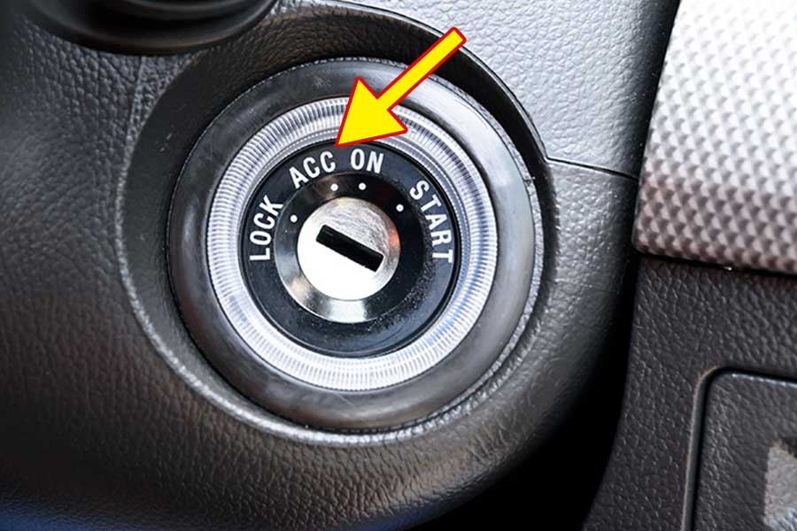
- Ignition Switch: The heart of the system. It's a multi-position switch that connects different circuits depending on its position (LOCK, ACC, ON, START).
- ACC Terminal: The specific contact within the ignition switch that provides power only when the switch is in the ACC position.
- Fuse: A critical safety device. The ACC circuit will always have a fuse protecting it from overcurrent. The fuse rating (e.g., 10A, 15A) determines the maximum current the circuit can handle. Exceeding this can blow the fuse, preventing damage to other components.
- Wiring: Copper wires carry the electrical current from the ignition switch, through the fuse, and to the accessories. Wire gauge (thickness) is important; thicker wires can handle more current.
- Accessories: The devices powered by the ACC circuit. Common examples include the radio, climate control blower motor (sometimes), power windows (sometimes), and auxiliary power outlets.
- Relays (Sometimes): For high-current accessories, a relay might be used. The ACC circuit powers the relay's coil, which then closes a separate, heavier-gauge circuit to power the accessory directly from the battery. This protects the ACC circuit from being overloaded.
Decoding the Wiring Diagram: Lines, Colors, and Symbols
Understanding wiring diagrams is crucial for working with any automotive electrical system. Here's a breakdown of common symbols and conventions:
- Lines: Represent wires. Thicker lines might indicate heavier-gauge wires (carrying more current). Dashed lines often represent ground connections.
- Colors: Wire colors are standardized (though variations exist). Common colors include red (typically power), black (typically ground), yellow, blue, green, and white. A wiring diagram will have a color code legend. For example, "RD/WT" means a red wire with a white stripe.
- Symbols:
- Battery: Represented by alternating long and short parallel lines.
- Fuse: Represented by a zig-zag line within a rectangle.
- Resistor: Represented by a zig-zag line.
- Ground: Represented by various symbols, often resembling an upside-down Christmas tree or a series of decreasing horizontal lines.
- Switch: Represented by a line that can be connected or disconnected to another line. The ignition switch symbol is more complex, showing multiple positions and connections.
- Relay: Represented by a coil and a switch. The coil, when energized, closes the switch.
- Connector: Represented by a circle or square.
When looking at a wiring diagram, pay close attention to the direction of current flow. Typically, it flows from the battery (positive terminal), through the circuit components, and back to the battery (negative terminal, or ground). Tracing this flow helps you understand how the circuit works and identify potential problems.
How the ACC Circuit Works
When the ignition switch is in the LOCK position, the ACC circuit is completely disconnected. No power flows to any accessories. This is the "off" state.
Turning the key to the ACC position connects the ACC terminal in the ignition switch to the power source (usually the battery, through a main fuse or distribution block). This energizes the ACC circuit. Power flows through the ACC fuse, then to the various accessories connected to the circuit. The accessories can now function – you can turn on the radio, use the power outlet, etc. The engine is not running in this position.
Turning the key to the ON position typically keeps the ACC circuit energized. The ON position powers additional circuits necessary for the engine to run (like the fuel pump, ignition system, and engine control unit (ECU)).
Turning the key to the START position engages the starter motor to crank the engine. In some vehicles, the ACC circuit might be temporarily disconnected during starting to provide maximum power to the starter. Once the engine starts and the key is released back to the ON position, the ACC circuit is re-energized.
Real-World Use: Basic Troubleshooting Tips
Here are a few troubleshooting scenarios where understanding the ACC circuit comes in handy:
- No power to accessories in ACC position:
- Check the ACC fuse. This is the most common cause. Use a multimeter to test the fuse for continuity. If it's blown, replace it with a fuse of the same rating.
- Check the ignition switch. Use a multimeter to verify that power is reaching the ACC terminal on the switch when the key is in the ACC position. If not, the ignition switch might be faulty.
- Check the wiring. Look for any damaged or corroded wires in the ACC circuit. Use a multimeter to check for voltage at various points in the circuit.
- Check the ground connection. Make sure the accessories have a good ground connection.
- Accessory drains the battery when the car is off: This indicates a parasitic drain.
- Disconnect devices powered by the ACC circuit one by one to see if the drain stops. If it does, the last device disconnected is likely the source of the problem.
- Use a multimeter to measure the current draw from the battery when the car is off. This will help you quantify the drain.
- Radio only works when the car is ON, not in ACC: This often points to a wiring issue. The radio might be wired to the ON circuit instead of the ACC circuit. Double-check the wiring diagram and correct the connections.
Safety: Respect the Electrical System
Working with automotive electrical systems can be dangerous. Here are some important safety precautions:
- Disconnect the battery: Before working on any electrical circuits, disconnect the negative battery terminal. This prevents accidental shorts and shocks.
- Use insulated tools: Always use tools with insulated handles to prevent electric shock.
- Never bypass fuses: Fuses are there to protect the circuit. Never replace a fuse with a higher-rated fuse or bypass it altogether. This can cause a fire.
- Be careful when working around airbags: Airbags are deployed by explosive charges. If you're working near an airbag, take extra precautions to avoid accidentally triggering it. Consult the vehicle's service manual for specific instructions.
- Understand polarity: Automotive electrical systems are typically negative ground. This means the negative battery terminal is connected to the vehicle's chassis. Always connect wires with the correct polarity to avoid damaging components.
- High-current circuits, especially those related to the starter motor, are very dangerous. Respect the power, and proceed with caution. If you're not comfortable working on these circuits, seek professional help.
This should provide you a solid introduction to your car's ACC circuit, its purpose, troubleshooting, and associated safety considerations.
To help you in your diagnosis and/or modification, we have the wiring diagram file available. You can download it by clicking HERE (link Placeholder). The diagram should provide you with valuable information for your specific vehicle.