What Is Afs In A Car
Adaptive Front-lighting System (AFS) – even if you're a seasoned DIY mechanic, you might not be intimately familiar with the ins and outs of this system. But with modern vehicles increasingly relying on advanced driver-assistance systems (ADAS), understanding AFS is becoming crucial. This article aims to demystify AFS, equipping you with the knowledge to diagnose issues, perform basic troubleshooting, and appreciate the technology behind it.
Purpose and Why Understanding AFS Matters
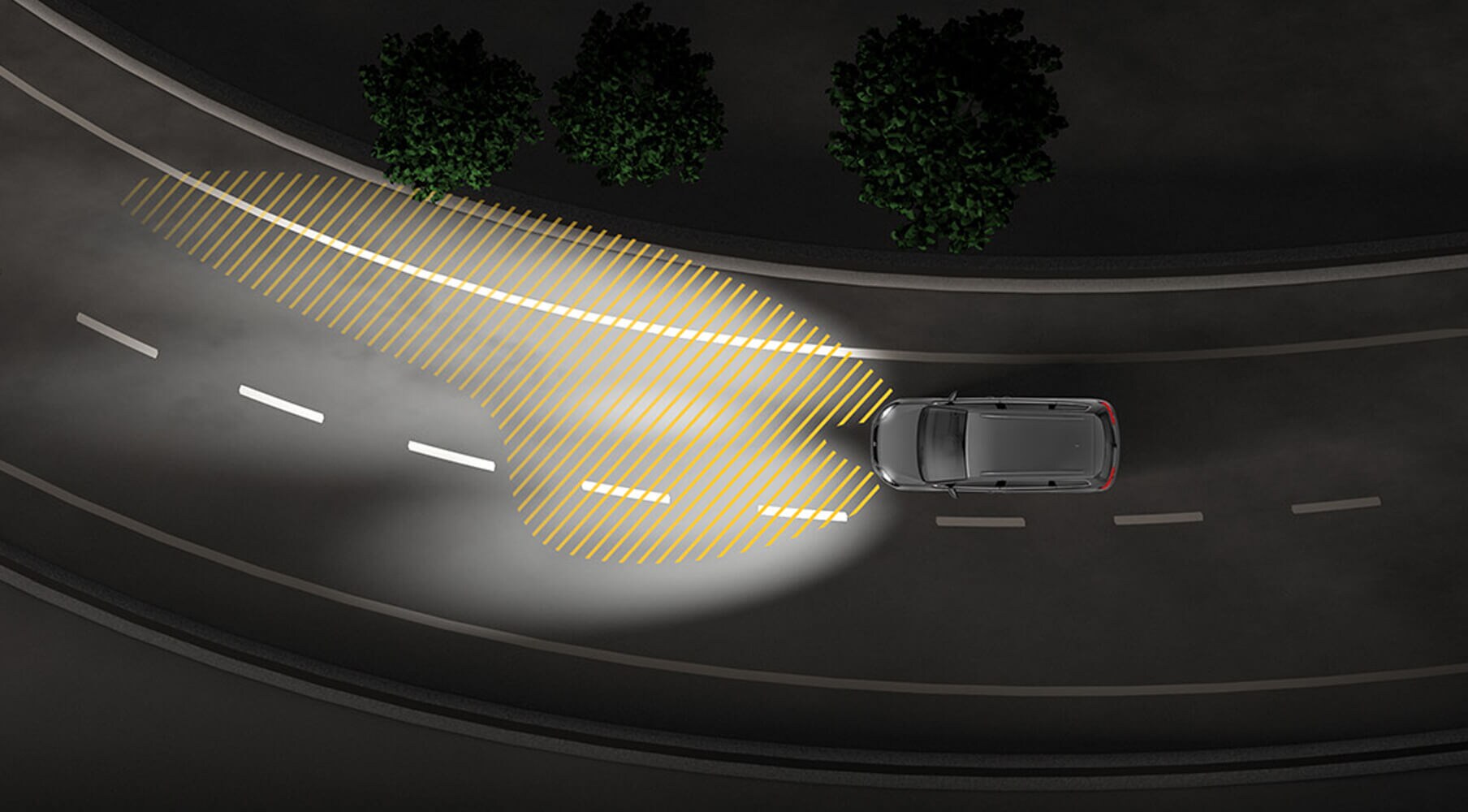
The primary purpose of AFS is to enhance visibility while driving, especially in low-light conditions and around corners. Unlike traditional headlights, AFS dynamically adjusts the headlight beam based on steering input, vehicle speed, and sometimes even GPS data. This active adjustment ensures that the road ahead is better illuminated, improving reaction time and potentially preventing accidents.
Understanding AFS is important for several reasons:
- Diagnosis and Repair: When your AFS malfunctions (often indicated by a warning light on the dashboard), understanding the system's components allows you to pinpoint the source of the problem, avoiding costly trips to the dealership for simple fixes.
- Modification and Customization: If you're interested in modifying your vehicle's lighting system, understanding how AFS integrates with the car's electronics is essential to ensure compatibility and avoid unintended consequences.
- General Car Knowledge: As cars become more sophisticated, understanding advanced systems like AFS helps you become a more informed car owner and DIY mechanic.
- Safety: Understanding the system helps you recognize when it is malfunctioning and therefore helps you to make informed decisions to stay safe when driving in compromised conditions.
Key Specs and Main Parts
AFS systems can vary in complexity, but they generally consist of the following components:
- Headlight Assemblies: These are not your standard headlights. They contain the actuators that physically move the headlight beam horizontally and/or vertically.
- Steering Angle Sensor: This sensor, usually part of the electronic power steering (EPS) system, provides information about the steering wheel angle.
- Vehicle Speed Sensor: This sensor provides data about the car's current speed.
- AFS Control Module: This is the "brain" of the system. It receives data from the sensors and calculates the optimal headlight position. It then sends commands to the headlight actuators.
- Actuators (Motors or Stepper Motors): These are small electric motors that physically move the headlight beam within the headlight assembly.
- Leveling Sensors (Optional): Some AFS systems use leveling sensors (usually located on the suspension) to compensate for vehicle load and ensure the headlights are properly aimed.
- GPS (Optional): Some advanced systems use GPS data to anticipate upcoming curves and adjust the headlights accordingly.
- Yaw Rate Sensor (Optional): Provides information about the vehicle's rotation around its vertical axis, which can be used to improve AFS accuracy during dynamic maneuvers.
Key Specs to Consider:
- Actuator Range: The range of motion that the actuators can achieve, measured in degrees. A wider range allows for more aggressive cornering illumination.
- Response Time: The speed at which the headlights adjust to changes in steering angle or vehicle speed. A faster response time provides a more seamless and natural driving experience.
- Power Consumption: The amount of electrical power consumed by the AFS system. This is especially important for electric vehicles (EVs) and hybrids, where energy efficiency is a key concern.
Symbols and Circuit Diagrams
Understanding circuit diagrams is crucial for diagnosing AFS issues. Here's a breakdown of common symbols and conventions:
- Lines: Represent wires. Thicker lines usually indicate wires carrying higher current.
- Colors: Each color corresponds to a specific wire function. A wiring diagram's color code legend is essential. For example, red might be power, black might be ground, and specific colors like blue/white or green/yellow might indicate signals for specific sensors.
- Icons: Represent components. Common icons include:
- Resistors: Zigzag line.
- Capacitors: Two parallel lines.
- Relays: A coil and a switch.
- Ground: Series of decreasing horizontal lines connected to one vertical line.
- Sensors: Often represented by a box with an arrow indicating the parameter being measured.
- ECU (Electronic Control Unit): Represented as a box with pins coming out.
- Connectors: Usually shown as circles or rectangles connecting wires. Understanding connector locations is vital for checking connections.
Voltage and Ground Symbols: Pay close attention to symbols indicating voltage (+12V, +5V, etc.) and ground. These are essential for understanding the power distribution within the AFS system.
Example Scenario: If you see a symbol for the steering angle sensor connected to the AFS control module by a wire labeled "Steering Angle Signal" with a color code of blue/red, it tells you the color of the wire you need to test to verify that there is a good signal.
How It Works
The AFS system operates in a closed-loop control system. Here's a simplified explanation:
- Sensor Input: Sensors (steering angle, vehicle speed, leveling sensors, etc.) continuously monitor driving conditions.
- Data Processing: The AFS control module receives data from the sensors and uses a pre-programmed algorithm (often a complex mathematical model) to determine the optimal headlight position.
- Actuator Control: The control module sends signals to the actuators in the headlight assemblies. These actuators, usually stepper motors, precisely move the headlight beam horizontally and/or vertically.
- Feedback (in some systems): Some advanced systems use feedback sensors within the headlight assembly to verify that the headlights have reached the desired position. This ensures accurate beam control.
The algorithm used by the AFS control module typically considers factors like:
- Steering Angle: A greater steering angle results in a larger headlight adjustment.
- Vehicle Speed: At higher speeds, the headlights may be adjusted more aggressively to provide better visibility around corners.
- Vehicle Load: Leveling sensors compensate for changes in vehicle load to maintain proper headlight aim.
Real-World Use: Basic Troubleshooting Tips
If your AFS warning light is illuminated, here are some basic troubleshooting steps you can take:
- Visual Inspection: Check the headlight assemblies for any obvious damage or loose connections.
- Scan for Codes: Use an OBD-II scanner to read diagnostic trouble codes (DTCs) related to the AFS system. Common codes might indicate a faulty steering angle sensor, a malfunctioning actuator, or a problem with the control module.
- Check Connections: Inspect the connectors for the steering angle sensor, vehicle speed sensor, and headlight assemblies. Look for corrosion or loose pins.
- Test Actuators: Some scanners allow you to manually activate the headlight actuators. If an actuator doesn't respond, it may be faulty.
- Check Fuses and Relays: Refer to your vehicle's owner's manual to locate the fuses and relays associated with the AFS system. Check for blown fuses or faulty relays.
Common Issues:
- Faulty Steering Angle Sensor: This is a common cause of AFS problems.
- Malfunctioning Actuators: Actuators can wear out over time or become damaged by water intrusion.
- Wiring Problems: Damaged or corroded wiring can disrupt communication between the sensors, control module, and actuators.
Safety Considerations
High-Voltage Components: While AFS itself doesn't typically involve high-voltage components, it's often integrated with other systems that do, such as the HID (High-Intensity Discharge) or LED headlights. Exercise extreme caution when working around these components. HID bulbs, in particular, operate at very high voltages and can deliver a dangerous shock even when the car is turned off.
Disconnect the Battery: Before working on any electrical components in your car, disconnect the negative battery terminal to prevent accidental shorts or shocks.
Consult the Service Manual: Always refer to your vehicle's service manual for specific instructions and safety precautions related to the AFS system.
Proper Headlight Aim: After working on the AFS system, it's crucial to ensure that the headlights are properly aimed. Misaligned headlights can reduce visibility and blind other drivers.
We have a detailed AFS system diagram available for download. It includes component locations, wiring diagrams, and troubleshooting flowcharts. This diagram can be an invaluable tool for diagnosing and repairing AFS issues on your specific vehicle model. Contact us to receive the file.