What Is An Idle Control Valve
Alright, let's talk about the Idle Control Valve (ICV). If you're diving into engine tuning, troubleshooting rough idling, or even just trying to understand how your car maintains a smooth idle, understanding the ICV is crucial. This component plays a vital role in ensuring your engine runs smoothly when your foot's off the gas. We're going to break down what it is, how it works, and how to troubleshoot it, empowering you to tackle common idle-related issues.
Purpose and Importance
The primary purpose of the Idle Control Valve is to regulate the engine's idle speed. When your engine is idling – meaning running without you pressing the accelerator – it still needs a certain amount of air to mix with fuel to keep running. However, with the throttle plate closed, the usual airflow path is restricted. The ICV provides an alternate path for air to bypass the throttle plate, allowing the engine to maintain a stable idle speed. This is particularly important because different engine loads (e.g., air conditioning, power steering pump) demand different idle speeds to prevent stalling. Think of it as a miniature gatekeeper, carefully managing airflow to keep your engine purring smoothly. Understanding this, you can see why this knowledge is crucial for diagnosing and repairing issues that could range from poor fuel economy to stalling at stop signs.
Key Specs and Main Parts
Let's delve into the ICV's anatomy. While specific designs vary between manufacturers and even across different engine models, the core components and principles remain the same. Key specifications often include:
- Voltage: Typically operates on 12V DC.
- Resistance: Ohm readings can be used to check the solenoid's integrity.
- Flow Rate: Measured in cubic feet per minute (CFM) or liters per minute (LPM), this indicates the valve's air-bypassing capacity.
The main parts generally consist of:
- Valve Body: The housing that contains all the other components. It is usually made of aluminum or plastic.
- Actuator: This is what actually moves the valve. There are two main types:
- Solenoid-based: These use an electromagnetic coil to move a plunger or valve.
- Stepper Motor-based: These use a small electric motor to precisely control the valve's position in incremental steps. These are generally more precise.
- Valve (Plunger, Rotary Valve, Butterfly Valve): The actual component that restricts or allows airflow. The specific type of valve varies based on the ICV design.
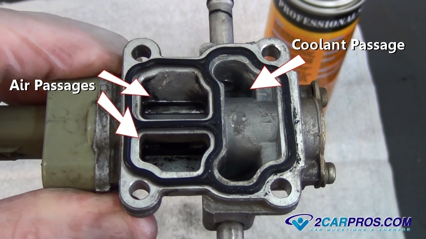
- Air Passages: The channels within the valve body that allow air to bypass the throttle plate.
- Connector: Connects the ICV to the Engine Control Unit (ECU).
How It Works
The ICV's operation is governed by the ECU. The ECU monitors various engine parameters, such as engine speed (RPM), coolant temperature, throttle position, and electrical load (A/C, headlights), to determine the optimal idle speed. It then sends a signal to the ICV to adjust the amount of air bypassing the throttle plate. Here's a breakdown based on actuator type:
- Solenoid-based ICV: The ECU controls the current flowing through the solenoid. A higher current opens the valve further, allowing more air to bypass the throttle. A lower current closes the valve. The ECU rapidly pulses the solenoid (Pulse Width Modulation or PWM) to control the average current and therefore the valve opening precisely.
- Stepper Motor-based ICV: The ECU sends a series of pulses to the stepper motor, causing it to rotate in small, precise increments. This rotation directly controls the valve's position, allowing for very fine adjustments to the idle speed.
As the engine warms up, the ECU gradually reduces the amount of air bypassing the throttle plate, as the engine requires less air to maintain a stable idle when warm. When electrical loads are applied (e.g., turning on the air conditioning), the ECU increases the idle speed to compensate for the increased engine load, preventing stalling. In essence, the ICV dynamically adjusts the airflow to maintain a consistent idle RPM regardless of engine temperature or load.
Real-World Use – Basic Troubleshooting
Here are some common symptoms of a faulty ICV and how to troubleshoot them:
- Rough or unstable idle: The engine RPM fluctuates erratically when idling.
- Stalling at idle: The engine stalls when you take your foot off the gas.
- High idle speed: The engine RPM is consistently higher than normal when idling.
- Check Engine Light: A diagnostic trouble code (DTC) related to the ICV may be stored in the ECU.
Here are some basic troubleshooting steps you can take:
- Visual Inspection: Check the ICV for any obvious signs of damage, such as cracks, broken connectors, or corrosion. Also, inspect the vacuum lines connected to the ICV for leaks.
- Cleaning: A dirty ICV can cause it to stick or malfunction. Use a carburetor cleaner or throttle body cleaner to carefully clean the valve and air passages. Be careful not to get cleaner into the electrical connector.
- Electrical Testing: Use a multimeter to check the resistance of the ICV's solenoid or stepper motor. Compare your readings to the manufacturer's specifications. Also, check for voltage at the ICV connector when the engine is running.
- Scan for Diagnostic Trouble Codes (DTCs): Use an OBD-II scanner to check for any DTCs related to the ICV. These codes can provide valuable clues about the nature of the problem.
- Check Vacuum Hoses: Vacuum leaks can cause erratic idling. Inspect all vacuum hoses connected to the intake manifold and ICV for cracks or disconnections.
If these steps don't resolve the issue, you may need to replace the ICV. However, be sure to properly diagnose the problem before replacing any parts.
Safety Considerations
Working on the ICV involves working around a running engine and electrical components, so it's crucial to prioritize safety:
- Disconnect the negative battery terminal before starting any work to prevent electrical shocks or short circuits.
- Work in a well-ventilated area when using cleaning solvents, as they can be harmful to breathe.
- Be careful when working around hot engine parts, such as the exhaust manifold.
- Avoid spraying cleaning solvents directly into the ICV's electrical connector, as this can damage the electrical components.
- Never probe electrical connectors with sharp objects, as this can damage the connector pins.
Diagram Availability
To further assist you in understanding the ICV, we have a detailed diagram available for download. This diagram provides a visual representation of the ICV's components, air passages, and electrical connections. It can be a valuable resource for troubleshooting and repairing ICV-related issues. With this resource you can more readily understand your vehicle’s idling system. Please note that specific designs may vary, but the fundamental principles remain consistent across various vehicles.