What Is Clock Spring In Car
Alright, let's dive into the fascinating, and sometimes frustrating, world of the clock spring in your car. As an experienced DIYer, you've probably encountered steering wheel issues, airbag lights, or non-functioning steering wheel controls. Chances are, the clock spring is involved. This article will give you a detailed understanding of what it is, how it works, and how to troubleshoot basic problems.
Purpose and Why It Matters
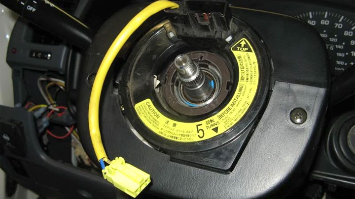
The clock spring, also known as a steering wheel module or contact reel, is a crucial component in your car's steering system. Its primary purpose is to maintain an electrical connection between the steering wheel and the vehicle's electrical system while allowing the steering wheel to rotate freely. Think of it as a rotating electrical connector. Without it, you wouldn't be able to control essential functions located on your steering wheel.
Why does this matter for repairs and learning? Well, diagnosing and replacing a faulty clock spring can save you money compared to taking your car to a mechanic. Understanding its function is crucial when troubleshooting issues like:
- Airbag warning lights: A common symptom of a failing clock spring.
- Non-functional steering wheel controls: Horn, radio controls, cruise control, etc.
- Loss of turn signal auto-cancel: The mechanism that automatically turns off your turn signal after completing a turn.
- Erratic behavior: Intermittent or unpredictable functionality of steering wheel-mounted components.
Key Specs and Main Parts
A typical clock spring assembly consists of several key components:
- Housing: This is the outer casing that protects the internal components of the clock spring. It's usually made of durable plastic.
- Spiral-wound ribbon cable: This is the heart of the clock spring. It's a flexible, flat cable wound in a spiral shape. This design allows the cable to extend and retract as the steering wheel turns, maintaining a constant electrical connection. Think of it like a coiled phone cord, but flat and electrical.
- Connectors: These are the points where the clock spring connects to the vehicle's wiring harness and the steering wheel components. They are typically multi-pin connectors.
- Rotation sensor (optional): Some vehicles have a rotation sensor integrated into the clock spring assembly. This sensor provides information about the steering wheel's position to the vehicle's computer, which is used for systems like electronic stability control (ESC).
- Slip ring (on some models): A conductive ring allowing connection to a rotating part, typically found in older designs alongside the ribbon cable.
Key specifications often include the number of circuits (wires) in the ribbon cable, the maximum rotation angle, and the voltage and current ratings. These specs are critical when sourcing a replacement part. Always ensure the replacement is a direct fit and matches the original specifications for your vehicle.
How It Works
The clock spring's operation is surprisingly simple in concept. The spiral-wound ribbon cable is housed within the assembly. As the steering wheel rotates, the inner end of the cable rotates with it, while the outer end remains fixed to the vehicle's chassis. The spiral design allows the cable to unwind and rewind as needed, maintaining electrical continuity. The ribbon cable contains multiple conductors, each dedicated to a specific function, such as the airbag, horn, and steering wheel controls.
To delve a bit deeper, the number of conductors directly relates to the complexity of the steering wheel features. A vehicle with basic functions might only require a few conductors, while a vehicle with advanced features like adaptive cruise control and heated steering wheel will require significantly more. The cable material itself is chosen for its flexibility and electrical conductivity, typically a copper alloy. The insulation on the ribbon cable prevents shorts and ensures reliable signal transmission.
The rotation sensor, when present, uses a magnetic or optical encoder to detect the steering wheel's position. This information is transmitted to the vehicle's ECU (Engine Control Unit) or other control modules, enabling features like ESC and variable power steering.
Real-World Use: Basic Troubleshooting Tips
Here are some basic troubleshooting tips if you suspect a faulty clock spring:
- Visual inspection: Check the clock spring assembly for any signs of damage, such as cracks or broken connectors.
- Check the airbag light: If the airbag light is on, use an OBD-II scanner capable of reading airbag codes. A code related to the clock spring or steering angle sensor is a strong indicator of a problem.
- Test the horn: If the horn doesn't work, it could be a problem with the clock spring.
- Test steering wheel controls: Check if any of the steering wheel controls (radio, cruise control, etc.) are not functioning.
- Continuity test: (Use extreme caution, disconnect the battery and consult your vehicle's repair manual) With the clock spring disconnected, you can use a multimeter to perform a continuity test on the ribbon cable's individual conductors. This can help identify broken or damaged wires. You need to know the pinout configuration of your clock spring to perform this test correctly.
Important Note: Before attempting any repairs, always disconnect the negative battery terminal and allow sufficient time for the system to discharge (typically 15-30 minutes) to avoid accidental airbag deployment. Refer to your vehicle's service manual for specific instructions and warnings.
Safety
The airbag system is a critical safety component, and improper handling of the clock spring can have serious consequences. The airbag is connected through the clock spring. Never attempt to repair a damaged clock spring; always replace it with a new unit. A malfunctioning clock spring can cause the airbag to deploy unexpectedly or, worse, fail to deploy in an accident. When replacing the clock spring, it's crucial to follow the manufacturer's instructions carefully. This typically involves centering the clock spring before installation to ensure proper operation and prevent damage to the ribbon cable. Mishandling the airbag circuit can lead to personal injury.
Diagrams and Further Learning
Clock spring diagrams are invaluable for understanding the pinout configuration, internal wiring, and connector locations. These diagrams are usually found in your vehicle's service manual or online databases specific to your car's make and model. The diagram will typically show:
- Pin assignments: Which pin corresponds to which function (airbag, horn, controls, etc.)
- Wiring color codes: The color of each wire within the ribbon cable.
- Connector types: The type and number of pins on each connector.
Understanding the diagram is crucial when performing continuity tests or troubleshooting wiring issues.
We have a general schematic available for download which provides a broad overview. Keep in mind you will need to source the diagram specific to your vehicle's year, make, and model for accurate repair information. You can download the general schematic here: [Insert download link placeholder here].
With a solid understanding of the clock spring, its function, and potential issues, you're well-equipped to tackle basic troubleshooting and replacement tasks. Remember to always prioritize safety and consult your vehicle's service manual for specific instructions.