What Is Ds On Nissan Altima
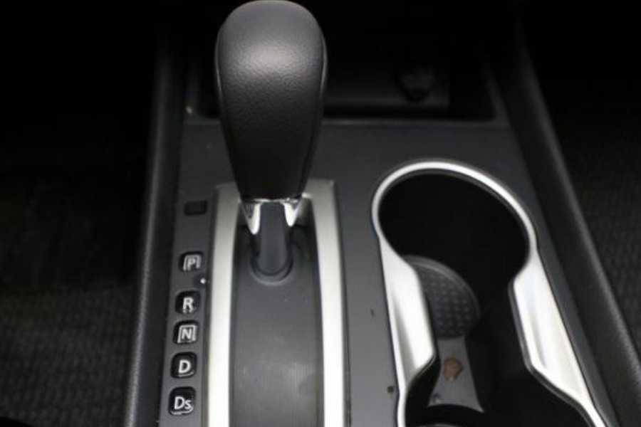
Alright, let's dive into the "Ds" indicator on your Nissan Altima's instrument cluster. This little light, when illuminated, indicates that the transmission is in "Drive" mode. But there's more to it than just knowing your car is moving forward. Understanding the systems connected to this indicator can be invaluable for diagnostics, repairs, and even basic troubleshooting.
Purpose of Understanding the "Ds" System
Why bother learning about the "Ds" indicator circuit? Several reasons. Firstly, if the "Ds" light doesn't illuminate when you shift into Drive, or conversely, stays illuminated when it shouldn't, it points to a problem somewhere in the system. Secondly, understanding how this indicator ties into the transmission control module (TCM), shift interlock system, and other components provides a solid foundation for more complex diagnostics down the road. Finally, having access to the relevant wiring diagrams allows you to trace circuits, check for voltage drops, and pinpoint the source of electrical issues that could be affecting not just the indicator, but potentially the entire transmission operation.
Key Specs and Main Parts
The "Ds" indicator circuit is relatively simple but interconnected. Here's a breakdown of the key components:
- Transmission Control Module (TCM): The brain of the operation. The TCM monitors various sensors (wheel speed sensors, throttle position sensor, etc.) and controls the transmission solenoids to shift gears. It's also responsible for signaling the instrument cluster to illuminate the "Ds" indicator.
- Inhibitor Switch (also known as Neutral Safety Switch or Park/Neutral Position Switch): This switch is mounted on the transmission and indicates the selected gear position to the TCM. It's a crucial component because it prevents the engine from starting unless the transmission is in Park or Neutral and also tells the TCM which gear has been selected.
- Instrument Cluster: Houses the "Ds" indicator (an LED or small incandescent bulb) and receives the signal from the TCM to illuminate it.
- Wiring Harness: The network of wires connecting all the components. This is where you'll be tracing circuits and checking for continuity.
- Shift Interlock Solenoid: Prevents the shifter from being moved out of Park unless the brake pedal is depressed. Although not directly part of the "Ds" indicator circuit, a malfunctioning shift interlock can sometimes mimic transmission-related issues and can be indirectly connected to the same power sources.
Symbols and Diagram Interpretation
Wiring diagrams use standardized symbols to represent electrical components. Understanding these symbols is crucial for effective troubleshooting. Here are some common symbols you'll encounter in a Nissan Altima wiring diagram:
- Solid Lines: Represent wires. Thicker lines may indicate wires carrying higher current.
- Dotted Lines: May represent shielded wires or wires that are part of a data communication network (CAN bus).
- Circles with Numbers or Letters: Represent connectors. These connectors are where wires join together, and they are prime locations to check for continuity and voltage.
- Resistors: Zigzag lines.
- Capacitors: Two parallel lines, one curved and one straight.
- Ground Symbol: Usually a series of stacked horizontal lines getting smaller as they descend. This indicates the point where the circuit is grounded to the vehicle's chassis.
- Fuse Symbol: A small "S" shape within a rectangle.
- Relay Symbol: A coil of wire and a switch mechanism.
- Colors: Wires are often color-coded. Common colors include Black (BLK) for ground, Red (RED) for power, and various other colors for signal wires. The diagram will have a legend explaining the color codes.
Pay close attention to the wiring diagram's legend. This will tell you what each symbol represents and the wire color codes used in the diagram. Understanding the legend is essential for accurately tracing circuits.
How It Works
Here's a simplified explanation of how the "Ds" indicator works:
- The driver shifts the gear selector into "Drive" (D).
- The Inhibitor Switch detects the selected gear position and sends a signal to the TCM.
- The TCM processes this signal, along with other sensor inputs, and determines the appropriate gear.
- The TCM then sends a signal to the instrument cluster to illuminate the "Ds" indicator. This signal is typically a voltage applied to the indicator bulb or LED.
- The instrument cluster receives the signal and illuminates the "Ds" indicator, informing the driver that the vehicle is in Drive.
This entire process is dependent on proper wiring, functioning sensors, and a healthy TCM. A break in any of these components can disrupt the system and cause the "Ds" indicator to malfunction.
Real-World Use: Basic Troubleshooting Tips
Let's say the "Ds" indicator on your Altima isn't lighting up when you put the car in Drive. Here are some basic troubleshooting steps you can take:
- Check the Fuses: Locate the fuse box diagram (usually in the owner's manual or on the fuse box cover) and identify the fuse(s) related to the instrument cluster and transmission control system. Check for blown fuses and replace them with the correct amperage.
- Inspect the Inhibitor Switch: The Inhibitor Switch is often located on the side of the transmission where the shift linkage connects. Visually inspect the switch for any damage or loose connections. You can use a multimeter to check the switch's continuity for each gear position. You’ll need the wiring diagram to identify the correct pins to test.
- Check the Wiring: Inspect the wiring harness and connectors leading to the instrument cluster, TCM, and Inhibitor Switch. Look for any signs of damage, corrosion, or loose connections. Use a multimeter to check for continuity between different points in the circuit.
- Scan for Trouble Codes: Use an OBD-II scanner to check for any trouble codes related to the transmission or instrument cluster. Even if the "Ds" indicator is the only symptom, there may be underlying codes that can point you in the right direction.
Example Scenario: You scan the car and get a code indicating a faulty Inhibitor Switch. Using the wiring diagram, you locate the switch and test its continuity. You find that the switch isn't sending the correct signal when the car is in Drive. This confirms that the Inhibitor Switch is likely the culprit and needs to be replaced.
Safety Considerations
Working on automotive electrical systems can be dangerous. Here are some important safety precautions:
- Disconnect the Battery: Always disconnect the negative battery terminal before working on any electrical components. This will prevent accidental shorts and electrical shocks.
- Work in a Well-Ventilated Area: Some automotive fluids and chemicals can be harmful if inhaled. Work in a well-ventilated area and wear appropriate safety gear (gloves, eye protection).
- Use Proper Tools: Use high-quality tools that are in good condition. Damaged or worn tools can increase the risk of injury.
- Avoid Working on Live Circuits: Whenever possible, avoid working on circuits while they are energized. If you must work on a live circuit, use extreme caution and wear appropriate safety gear.
- Be Aware of Airbag Systems: Avoid tampering with airbag systems unless you are properly trained and equipped. Airbags can deploy unexpectedly and cause serious injury.
- High Voltage: Be extremely careful near the ignition system. The ignition coil can produce very high voltage that can be lethal.
Remember: If you are not comfortable working on electrical systems, it is best to consult a qualified mechanic.
Understanding the "Ds" indicator system in your Nissan Altima can empower you to diagnose and potentially fix minor issues yourself. However, always prioritize safety and consult a professional for complex repairs. Remember, this information is for educational purposes and should not be considered a substitute for professional automotive advice.
We have the complete wiring diagrams for your specific Altima model year. Understanding these will dramatically help your ability to troubleshoot the "Ds" system. You can download the diagram to get started!