What Is Intake On A Car
So, you want to dig into the intake system on your car? Smart move! Understanding the intake is crucial for everything from basic maintenance to performance upgrades. This article will break down the key components, function, and troubleshooting of a typical automotive intake system. We'll cover enough detail to arm you with the knowledge to tackle repairs and modifications with confidence.
Purpose of Understanding the Intake System
Why bother learning about your car's intake? Well, a solid understanding of the intake system is essential for several reasons. Firstly, it enables accurate diagnosis of engine performance issues. Symptoms like poor fuel economy, rough idling, or a lack of power often stem from problems within the intake system. Secondly, knowledge of the intake system empowers you to perform repairs and maintenance tasks yourself, potentially saving significant money on labor costs. Finally, for those interested in modifying their vehicle for increased performance, understanding the intricacies of the intake system is paramount. Whether you're upgrading to a cold air intake, porting the intake manifold, or installing forced induction, a thorough understanding is crucial for success. Moreover, understanding allows you to choose correct replacement parts from a catalog.
Key Specs and Main Parts
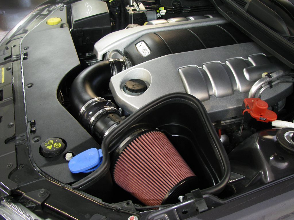
Let's get into the guts of the intake system. While specific designs vary between vehicles, the fundamental components remain consistent. Here's a breakdown of the key parts and their specifications:
1. Air Filter
The air filter is the intake system's first line of defense. Its primary function is to prevent dirt, dust, and debris from entering the engine. These contaminants can cause significant wear and damage to internal engine components. Air filters are typically constructed from paper, cotton gauze, or synthetic materials. Specifications include:
- Filtration Efficiency: Measured by the percentage of particles of a specific size that the filter can capture.
- Airflow Rate: The volume of air that can pass through the filter per unit time. Higher airflow generally improves engine performance, but can reduce filtration efficiency.
- Filter Material: Affects filtration efficiency, airflow, and lifespan.
2. Intake Ducting
Intake ducting channels air from the air filter to the throttle body. It's typically made of plastic or rubber. The design of the ducting can significantly impact airflow. Specifications include:
- Material: Heat resistance is important, especially near the engine.
- Diameter: Affects airflow volume and velocity.
- Smoothness: Smooth internal surfaces minimize airflow restriction.
3. Throttle Body
The throttle body controls the amount of air entering the engine. It contains a throttle plate that pivots to regulate airflow in response to the driver's accelerator pedal input. Specifications include:
- Bore Diameter: The diameter of the throttle bore, which directly impacts airflow capacity. Larger bore diameters are often used in performance applications.
- Throttle Position Sensor (TPS): A sensor that monitors the throttle plate's position and sends this information to the engine control unit (ECU).
4. Intake Manifold
The intake manifold distributes the air evenly to each of the engine's cylinders. It's a complex casting, typically made of aluminum or plastic, with runners that connect the throttle body to the cylinder head. Specifications include:
- Runner Length and Diameter: These dimensions influence the engine's torque curve. Longer runners generally improve low-end torque, while shorter runners enhance high-end horsepower.
- Plenum Volume: The volume of the plenum (the large chamber in the intake manifold) affects the engine's responsiveness.
- Material: affects weight and heat transfer.
5. Mass Airflow Sensor (MAF) or Manifold Absolute Pressure Sensor (MAP)
These sensors measure the amount of air entering the engine. The MAF sensor directly measures the mass of air, while the MAP sensor measures the pressure in the intake manifold. The ECU uses this information to calculate the correct amount of fuel to inject. Specifications include:
- Range: The range of airflow or pressure values that the sensor can accurately measure.
- Accuracy: The degree to which the sensor's readings match the actual airflow or pressure.
6. Fuel Injectors
Although technically part of the fuel system, fuel injectors reside in the intake manifold or directly in the cylinder head, injecting fuel into the intake air stream (or directly into the cylinder in direct injection systems). Specifications include:
- Flow Rate: Measured in lbs/hr or cc/min, indicating the amount of fuel the injector can deliver.
- Spray Pattern: The shape and distribution of the fuel spray, which affects combustion efficiency.
How It Works
The intake system's operation is relatively straightforward in principle. The engine, during its intake stroke, creates a vacuum (low pressure) inside the cylinder. This vacuum draws air through the air filter, into the intake ducting, through the throttle body (which is opened by the driver pressing the accelerator), and into the intake manifold. The intake manifold then distributes the air to each cylinder. The MAF or MAP sensor measures the amount of air entering the engine, providing critical data to the ECU. The ECU then uses this data, along with other sensor inputs (e.g., engine temperature, crankshaft position), to determine the optimal amount of fuel to inject. The fuel injectors spray fuel into the intake air stream, creating an air-fuel mixture that is drawn into the cylinder during the intake stroke. This mixture is then compressed and ignited, powering the engine.
In turbocharged or supercharged engines, the intake system includes a turbocharger or supercharger that compresses the intake air before it enters the throttle body. This forced induction system increases the density of the air, allowing the engine to burn more fuel and produce more power. Intercoolers are often used to cool the compressed air after it exits the turbocharger or supercharger, further increasing air density and power output.
Real-World Use – Basic Troubleshooting Tips
Here are some common intake system problems and how to troubleshoot them:
- Dirty Air Filter: Reduced airflow, poor fuel economy, sluggish acceleration. Solution: Replace the air filter regularly (check your owner's manual for recommended intervals).
- Vacuum Leaks: Rough idling, poor fuel economy, engine misfires. Solution: Inspect vacuum hoses for cracks or disconnections. Use a vacuum gauge to check for leaks. A smoke test can also pinpoint leaks.
- Faulty MAF or MAP Sensor: Poor fuel economy, engine misfires, stalling. Solution: Use a scan tool to check for error codes related to the MAF or MAP sensor. Check the sensor's wiring and connections. Test the sensor's output voltage.
- Sticking Throttle Body: Erratic idling, difficulty controlling engine speed. Solution: Clean the throttle body with throttle body cleaner. Check the throttle cable or electronic throttle control system.
Important Note: Always disconnect the negative battery terminal before working on any electrical components, including sensors.
Safety – Highlight Risky Components
The intake system is generally safe to work on, but there are a few components that require extra caution:
- Throttle Body: Be careful when cleaning the throttle body, as some cleaners can damage sensors. Always disconnect the battery before cleaning to prevent accidental throttle activation.
- MAF/MAP Sensors: These sensors are delicate and easily damaged. Handle them with care and avoid touching the sensing element.
- Working on a running engine: Never place hands near moving parts of a running engine, such as the throttle linkage.
- Hot Engine Components: The intake manifold can become extremely hot, especially after the engine has been running. Allow the engine to cool completely before working on the intake system.
Also, be aware of the potential for backfire when working with the intake. Though rare in modern vehicles with electronic fuel injection, a backfire can cause burns and damage to the intake system.
By understanding the components, function, and troubleshooting of the intake system, you'll be well-equipped to maintain and modify your vehicle for optimal performance. Remember, safety first!
We have a detailed diagram of a typical intake system available for download. This diagram provides a visual representation of the components and their relationship to each other. It's a valuable resource for understanding the system's layout and tracing the airflow path.