What Is Park Assist On A Vehicle
Alright, let's dive into park assist – that helpful (and sometimes frustrating) feature found on many modern vehicles. We're going to break down how it works, what the key components are, and even touch on some basic troubleshooting. Think of this as a deep-dive, but explained in a way that makes sense, even if you're not an electrical engineer. Consider this your go-to guide before attempting any repairs or modifications involving your vehicle's parking assist system. We'll cover not just the 'what,' but also the 'why' and 'how.'
Purpose of Understanding Park Assist Systems
Understanding the intricacies of your vehicle's park assist system is crucial for a few reasons. First, it allows for more informed troubleshooting. Instead of blindly replacing parts, you can use your knowledge to pinpoint the actual issue. Second, it empowers you to perform basic maintenance and potentially even some repairs yourself, saving you money and time at the mechanic. Third, if you're considering modifications or upgrades to your vehicle's electrical system, knowing how park assist integrates into the overall architecture is essential to avoid causing unintended consequences. Think about it – you wouldn't want to accidentally disable your ABS system while trying to improve your parking skills! The complexity warrants a solid comprehension.
Key Specs and Main Parts of a Park Assist System
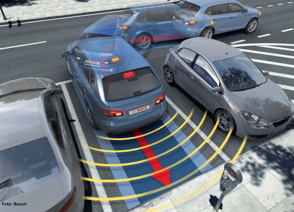
A typical park assist system, whether it's a basic rear-sensing system or a more advanced parallel parking assist feature, comprises several key components:
- Ultrasonic Sensors: These are the "eyes" of the system. They emit high-frequency sound waves that bounce off objects. The time it takes for the echo to return is used to calculate the distance.
- Control Module (ECU): The brain of the operation. This module receives signals from the sensors, processes the data, and determines the distance and position of obstacles. It then uses this information to provide alerts or, in advanced systems, to control the steering.
- Audible Alert System (Buzzer/Speaker): This provides audible warnings to the driver, usually increasing in frequency as the vehicle gets closer to an obstacle.
- Visual Display (Optional): Many systems include a visual display, often integrated into the infotainment screen, that shows the vehicle's proximity to obstacles. Some displays even show a top-down view of the vehicle and its surroundings.
- Steering Control System (For Advanced Systems): In parallel parking assist systems, this includes the power steering system, steering angle sensors, and actuators that allow the ECU to control the steering wheel directly. This is a considerably more complex system.
- CAN Bus Communication: Most modern park assist systems communicate with other vehicle systems (e.g., the transmission, ABS) via the CAN (Controller Area Network) bus. This allows the system to access information like vehicle speed and steering angle.
Key Specs: Important specifications to consider when diagnosing or modifying a park assist system include:
- Sensor Range: The maximum distance the sensors can effectively detect obstacles (typically a few meters).
- Sensor Frequency: The ultrasonic frequency used by the sensors (usually in the 40-60 kHz range).
- System Voltage: The operating voltage of the system (typically 12V).
- Communication Protocol: The specific CAN bus protocol used for communication.
Understanding Park Assist System Diagrams: Lines, Colors and Symbols
Reading a park assist system diagram is essential for troubleshooting and repair. Here's a breakdown of common symbols and conventions:
- Lines: Solid lines typically represent wires or electrical connections. Dashed lines may indicate shielding or ground connections. Thicker lines might represent power wires carrying larger currents.
- Colors: Wire colors are usually indicated by abbreviations (e.g., BLU for blue, RED for red, GRN for green). These colors are crucial for identifying the correct wires when probing or making connections.
- Symbols: Standard electrical symbols are used to represent components like sensors (often represented by a circle with a sound wave symbol), ECUs (typically a rectangle with pins representing inputs and outputs), and connectors (usually represented by interlocking shapes).
- Connectors: Connector diagrams are critical for identifying the pinout of each connector. These diagrams show the physical arrangement of the pins and their corresponding wire colors and functions.
- Grounding Points: Grounding points are usually represented by a triangle symbol. Ensuring good grounding is essential for proper system operation.
Example: Imagine a diagram showing a sensor connected to the ECU. A solid red line might represent the power supply wire, a solid black line might be the ground wire, and a solid blue line might be the signal wire carrying the distance information. A dashed line might represent the shielding around the signal wire.
How Park Assist Works: A Step-by-Step Explanation
Here’s a simplified explanation of how a basic park assist system works:
- Sensor Activation: When the vehicle is in reverse (or sometimes in forward gear at low speeds), the park assist system is activated.
- Ultrasonic Emission: The ultrasonic sensors emit sound waves.
- Echo Detection: The sensors detect the echoes that bounce back from nearby objects.
- Distance Calculation: The control module (ECU) measures the time it takes for the echoes to return. Knowing the speed of sound, it calculates the distance to each object. This calculation is based on the formula: Distance = (Speed of Sound * Time) / 2. The division by 2 accounts for the sound wave traveling to the object and back.
- Object Identification: Advanced systems use multiple sensors and sophisticated algorithms to determine the size and shape of the objects.
- Alert Generation: Based on the distance and position of the objects, the ECU generates audible and/or visual alerts. The closer the vehicle gets to an obstacle, the more frequent the audible alerts become.
- Steering Assistance (Advanced Systems): In parallel parking assist systems, the ECU uses the sensor data to calculate the optimal steering trajectory. It then controls the power steering system to automatically steer the vehicle into the parking space. This involves complex algorithms and feedback loops to ensure accurate and safe maneuvering.
Real-World Use: Basic Troubleshooting Tips
Here are some common park assist problems and potential troubleshooting steps:
- System Not Working:
- Check the fuse for the park assist system. A blown fuse is a common cause of failure.
- Check the wiring connections to the sensors and ECU. Look for loose connections, corrosion, or damaged wires.
- Scan the vehicle's computer for diagnostic trouble codes (DTCs) using an OBD-II scanner. DTCs can provide valuable clues about the source of the problem.
- False Alarms:
- Ensure the sensors are clean and free from dirt, mud, or ice. Obstructions can interfere with the sensor's ability to accurately detect objects.
- Check for damage to the sensor surfaces. Scratches or cracks can distort the sound waves.
- Some systems allow you to adjust the sensitivity of the sensors. Try reducing the sensitivity to minimize false alarms.
- Inaccurate Readings:
- Calibrate the sensors according to the manufacturer's instructions. Calibration ensures that the sensors are properly aligned and functioning correctly.
- Check for interference from other electronic devices. Some aftermarket devices can interfere with the sensor's signals.
Example: You're experiencing constant false alarms. First, check for any visible obstructions on the sensors. Clean them thoroughly. If the problem persists, use an OBD-II scanner to check for DTCs. A DTC related to a specific sensor might indicate a faulty sensor. Also check the wiring diagram to see if the sensor has a separate ground. Verify the ground is solid.
Safety Considerations: Highlighting Risky Components
Working on a park assist system involves dealing with electrical components, so safety is paramount:
- Disconnect the Battery: Before working on any electrical component, disconnect the negative terminal of the battery to prevent accidental shorts or electric shock.
- Handle Sensors Carefully: Ultrasonic sensors are delicate. Avoid dropping them or exposing them to excessive force.
- Avoid Water Intrusion: Protect the ECU and other electronic components from water damage. Water can cause corrosion and short circuits.
- Consult the Service Manual: Always refer to the vehicle's service manual for specific instructions and safety precautions.
- Power Steering System (Advanced Systems): Warning! Working on the power steering system in advanced park assist systems can be dangerous due to high pressures and potential for hydraulic fluid leaks. Exercise extreme caution and follow all safety guidelines. Improper handling can cause serious injury.
Remember that even seemingly low-voltage circuits can deliver a painful shock. Always prioritize safety when working on your vehicle.
We have a detailed wiring diagram for a common park assist system that you can download. It contains all the component locations, wiring configurations, and sensor specifications needed for effective troubleshooting and repair. Understanding that wiring diagram will make you well equipped to understand this technology.