What Is Passive Anti Theft System
Alright, let's dive into the world of Passive Anti-Theft Systems (PATS). For experienced DIYers and modders, understanding PATS is crucial for diagnostics, repairs, and even certain performance modifications. It's essentially your car's electronic gatekeeper, verifying the key before allowing the engine to start. This isn't just about preventing theft; a malfunctioning PATS can leave you stranded, so understanding how it works is invaluable.
Purpose and Relevance
Why are we discussing this? Well, having a solid grasp of the PATS allows you to:
- Troubleshoot Starting Problems: A PATS issue can mimic other mechanical or electrical problems. Knowing the system helps isolate the root cause.
- Perform Key Programming: Replacing a lost key often requires re-programming it to the PATS. Understanding the process is key.
- Understand Aftermarket Modifications: Some modifications, like remote starters, interact directly with the PATS. You need to know what's going on to avoid conflicts or bypass issues.
- General Automotive Knowledge: It's simply good to know how a vital system in your car functions.
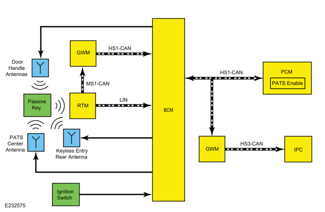
We have a detailed system diagram of a generic PATS available for you to download that will be a helpful visual aid as we go through the different components and how they work together.
Key Specs and Main Parts
A PATS isn't a single component; it's a system involving several interacting modules. Here's a breakdown of the main players:
- Transponder Key: This isn't just a piece of metal. Embedded within the key is a small transponder – a microchip that emits a unique radio frequency identification (RFID) signal.
- Transceiver (or PATS Module): Located near the ignition switch, the transceiver contains an antenna that interrogates the key when it's inserted. It sends a radio signal to the key's transponder.
- Powertrain Control Module (PCM): The PCM, also known as the Engine Control Unit (ECU), is the car's main computer. It receives the security code from the transceiver. The PCM is the ultimate authority; it decides whether or not to enable fuel injection and ignition.
- Security Indicator Lamp: Typically located on the instrument cluster, this light illuminates to indicate PATS status. Flashing lights often signal errors or system activation.
- Diagnostic Link Connector (DLC): This is the OBD-II port that a scan tool connects to in order to communicate with the car's computers, including PATS.
Symbols and Diagrams
Reading an electrical diagram can seem daunting at first, but it's all about understanding the basic symbols. Here’s a simplified overview:
- Solid Lines: Represent wires carrying electrical current. Thicker lines often indicate wires carrying more amperage.
- Dashed Lines: Usually represent data communication lines between modules (e.g., the data bus connecting the transceiver to the PCM).
- Ground Symbol: Looks like an upside-down Christmas tree. It indicates a connection to the vehicle's chassis ground, providing a return path for current.
- Component Boxes: Rectangles or squares represent individual components like sensors, modules, and relays. The component's name is usually written inside the box.
- Connectors: Shown as circles or squares where wires join. Often labeled with pin numbers.
- Colors: Wires are often color-coded (e.g., red for power, black for ground). The diagram usually includes a key to the color codes.
When reading the diagram, follow the lines to trace the flow of electricity and data between components. Note the voltage levels at different points (usually indicated on the diagram). This is crucial for troubleshooting.
How It Works
The PATS process unfolds in a specific sequence:
- Key Insertion: You insert the key into the ignition.
- Transceiver Activation: The transceiver module, located near the ignition switch, powers up and emits a radio frequency signal.
- Transponder Response: The RFID chip (transponder) in the key is energized by the transceiver's signal. It then transmits its unique security code back to the transceiver.
- Code Verification: The transceiver receives the code and sends it to the PCM via the vehicle's data bus.
- PCM Validation: The PCM compares the received code to its stored list of authorized key codes.
- Engine Enable: If the code matches, the PCM enables fuel injection and ignition, allowing the engine to start. If the code doesn't match, the PCM prevents the engine from starting by disabling these systems.
- Security Indicator: The security indicator light will illuminate briefly and then turn off (or stay off) to indicate successful key validation.
If the code is incorrect, the security light will typically flash or remain illuminated, and the engine will be disabled.
Real-World Use – Basic Troubleshooting Tips
If you're experiencing PATS-related problems, here are a few basic troubleshooting steps you can try:
- Check the Security Indicator Light: Pay close attention to the light's behavior when you turn the key. Is it flashing rapidly, staying on constantly, or not illuminating at all? This provides a clue.
- Try a Different Key: If you have a spare key, try using it. If the spare key works, the original key's transponder may be faulty.
- Check the Battery Voltage: Low battery voltage can sometimes interfere with PATS operation. Make sure your battery is fully charged.
- Inspect Wiring and Connections: Visually inspect the wiring and connectors around the transceiver and PCM for any signs of damage, corrosion, or loose connections.
- Use an OBD-II Scanner: A scan tool can retrieve diagnostic trouble codes (DTCs) related to the PATS. This is crucial for pinpointing the problem. Common codes might indicate a communication error between the transceiver and the PCM, or a key programming issue.
Common PATS Issues:
- Faulty transponder in the key
- Damaged or faulty transceiver module
- Wiring problems (e.g., broken wires, corroded connectors)
- PCM malfunction
- Key programming errors
Basic Troubleshooting Steps using an OBD-II scanner:
- Connect your OBD-II scanner to the DLC.
- Turn the ignition to the "ON" position (without starting the engine).
- Select the "Read Codes" or "Trouble Codes" option on your scanner.
- Look for codes related to the PATS, immobilizer, or security system. These codes often start with "B" (Body) or "U" (Network Communication).
- Note the codes and research their meaning.
- Clear the codes and try starting the engine. If the problem persists, the code will likely reappear.
Example Codes:
- B1600: PATS Ignition Key Transponder Signal is Not Received
- B1601: PATS Received Incorrect Key-Code from Key Transponder
- U0100: Lost Communication With ECM/PCM
Safety
Working on automotive electrical systems can be dangerous. Here are some key safety precautions:
- Disconnect the Battery: Before working on any electrical component, disconnect the negative battery terminal to prevent shorts and electrical shocks.
- Use Proper Tools: Use insulated tools designed for automotive electrical work.
- Be Careful with Airbags: Some components of the PATS may be located near airbags. Refer to the vehicle's service manual for proper airbag deactivation procedures before working in these areas. Improper handling of airbags can result in serious injury.
- High Voltage: While the PATS system itself operates on low voltage, be aware of other high-voltage components in the engine compartment (e.g., ignition coils).
Disclaimer: Working on automotive systems can be complex. If you're not comfortable with electrical troubleshooting, consult a qualified mechanic.
We have the PATS diagram file as mentioned earlier. You can download it by clicking here. Remember to always prioritize safety and consult your vehicle's service manual for specific procedures.