What Is The Clock Spring On A Car
For the seasoned DIY enthusiast, understanding the inner workings of your vehicle is not just a hobby; it's a necessity. And one component often overlooked, yet crucial for safety and convenience, is the clock spring. This article dives deep into the clock spring, providing you with the technical knowledge to diagnose, troubleshoot, and even replace it with confidence. Knowing how this diagram works is helpful for a variety of repairs and upgrades to your car, like swapping out the steering wheel or diagnosing why your horn stopped working.
What Exactly Is a Clock Spring?
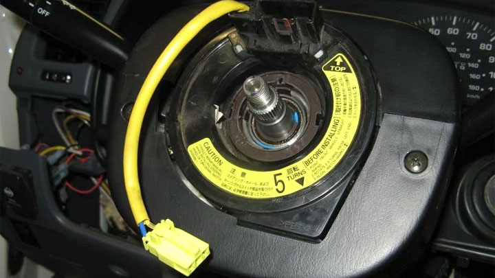
The clock spring, also known as the steering wheel module, airbag clock spring, or contact reel, is an electromechanical device located behind the steering wheel. It allows the steering wheel to rotate while maintaining a constant electrical connection to vital components mounted on or near the steering wheel. Think of it as a coiled ribbon cable that unspools and respools as you turn the wheel.
Key Specs and Main Parts
A typical clock spring consists of the following key components:
- Housing: A plastic or metal enclosure that protects the internal components from dust, debris, and physical damage.
- Rotor (or Reel): The rotating part of the assembly that's directly connected to the steering wheel.
- Stator: The stationary part that remains fixed to the steering column.
- Ribbon Cable (or Flat Cable): The flexible, multi-conductor cable that carries electrical signals between the rotor and stator. This is the heart of the clock spring.
- Connectors: Electrical connectors that link the clock spring to the vehicle's wiring harness. These usually include connectors for the airbag, horn, cruise control, and other steering wheel-mounted controls.
- Centering Mechanism (if equipped): Some clock springs have a mechanism to ensure the unit is properly centered during installation. Misalignment can lead to cable breakage.
Key specifications to consider when replacing a clock spring include:
- Number of Circuits: Indicates the number of individual wires within the ribbon cable. This determines how many features the clock spring can support (e.g., airbag, horn, radio controls, heated steering wheel).
- Operating Voltage: Typically 12V, but always verify compatibility with your vehicle's electrical system.
- Operating Temperature Range: Clock springs are designed to withstand a wide range of temperatures, but extreme conditions can shorten their lifespan.
- Rotation Angle: The maximum angle the steering wheel can rotate before the clock spring's ribbon cable is fully extended. Exceeding this limit will cause damage.
Symbols and Conventions
While a dedicated diagram of a clock spring might not use highly specialized symbols like a complex electrical schematic, understanding the general conventions is helpful:
- Lines: Represent electrical wires or the physical connections between components. Dashed lines may indicate shielded wires.
- Colors: Wiring diagrams use standard color codes to identify the function of each wire (e.g., red for power, black for ground). Pay close attention to these when disconnecting and reconnecting wires.
- Icons/Labels: Specific components like the airbag connector, horn connector, and cruise control connector will be labeled clearly. Diagrams often use abbreviations (e.g., "AIRBAG," "HORN," "CC") to save space.
- Arrows: May indicate the direction of current flow or the intended rotational direction of the steering wheel.
- Blocks: Simple rectangular or square boxes are often used to represent the rotor and stator.
How It Works: The Magic Behind the Spin
The core function of the clock spring is to maintain electrical continuity regardless of the steering wheel's position. This is achieved through the clever design of the ribbon cable. The cable is coiled inside the housing, allowing it to wind and unwind as the steering wheel is turned.
Here's a simplified breakdown:
- Steering Wheel Rotation: As you turn the steering wheel, the rotor of the clock spring rotates with it.
- Cable Winding/Unwinding: The ribbon cable either winds tighter or unwinds slightly within the housing, accommodating the rotational movement.
- Constant Connection: Despite the winding and unwinding, the ribbon cable maintains a constant electrical connection between the stator (connected to the vehicle's wiring harness) and the rotor (connected to the steering wheel controls).
- Signal Transmission: Electrical signals from the steering wheel controls (e.g., horn button, radio controls) travel through the ribbon cable to the vehicle's electronic control units (ECUs).
The key to the clock spring's functionality is the flexibility and durability of the ribbon cable. It must withstand countless cycles of winding and unwinding without breaking or losing conductivity. Quality clock springs use high-quality materials and manufacturing processes to ensure long-term reliability.
Real-World Use: Troubleshooting and Diagnosis
A malfunctioning clock spring can manifest in several ways. Here are some common symptoms:
- Airbag Warning Light: This is often the most critical symptom, as it indicates a potential problem with the airbag circuit. A faulty clock spring can prevent the airbag from deploying in a collision.
- Horn Malfunction: The horn may not work consistently or at all.
- Cruise Control Issues: Cruise control may not engage or may disengage intermittently.
- Steering Wheel Control Problems: Radio controls, phone controls, or other steering wheel-mounted functions may not work.
- Clicking or Grinding Noise: A worn or damaged clock spring may produce audible noises when the steering wheel is turned.
Basic Troubleshooting Tips:
- Visual Inspection: Carefully inspect the clock spring for any signs of physical damage, such as cracks, breaks, or frayed wires.
- Continuity Testing: Use a multimeter to check the continuity of each wire within the ribbon cable. A break in continuity indicates a faulty wire.
- Code Scanning: Use an OBD-II scanner to check for diagnostic trouble codes (DTCs) related to the airbag system or other steering wheel-mounted functions.
Important Note: Before performing any electrical testing, disconnect the negative battery cable to prevent accidental short circuits.
Safety: Handle with Extreme Care
The airbag system is a critical safety feature, and the clock spring plays a vital role in its proper functioning. Airbags contain explosive propellants, and improper handling can lead to accidental deployment, causing serious injury.
Key Safety Precautions:
- Disconnect the Battery: Always disconnect the negative battery cable and wait at least 15 minutes before working on the clock spring or any part of the airbag system. This allows the system's capacitors to discharge, reducing the risk of accidental deployment.
- Follow Manufacturer's Instructions: Consult your vehicle's repair manual or a reputable online resource for specific instructions on clock spring removal and replacement.
- Avoid Static Electricity: Static electricity can trigger airbag deployment. Ground yourself properly before touching any airbag components.
- Use Proper Tools: Use the correct tools for the job to avoid damaging the clock spring or surrounding components.
- Handle with Care: Treat the clock spring with care. Avoid dropping it or subjecting it to excessive force.
- Clock Spring Centering: If the clock spring has a centering mechanism, ensure it is properly centered before installation. Failure to do so can damage the ribbon cable.
- Professional Assistance: If you are not comfortable working on the airbag system, seek professional assistance from a qualified mechanic.
Ignoring these safety precautions can have severe consequences. When in doubt, err on the side of caution and consult a professional.
We have a detailed clock spring diagram available for download to further assist you with your repairs. This diagram provides a visual representation of the clock spring's components and their interconnections.