What Is The Ds On A Nissan Altima
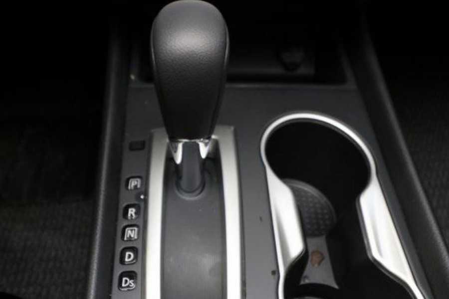
Alright, let's talk about the "Ds" on your Nissan Altima's shift lever. Now, "Ds" itself isn't a component or a diagnostic port. What we're really referring to is the Drive mode, and all the systems that allow you to efficiently and reliably move your Altima forward. Understanding the Drive mode, and particularly the relevant wiring diagrams and systems associated with it, is crucial for diagnosing transmission issues, modifying your car (especially if you're playing with TCU tuning), or just getting a deeper understanding of how your car operates. We've got a comprehensive wiring diagram for your Altima's transmission control system available for download – check the end of the article. This guide will walk you through understanding what that diagram means.
Purpose of Understanding the Drive System Diagram
Why bother learning all this? Well, understanding the Drive system diagram empowers you to:
- Diagnose Transmission Problems: From shift solenoid issues to sensor failures, the diagram helps you pinpoint the faulty component.
- Perform DIY Repairs: Armed with the diagram, a multimeter, and some know-how, you can tackle many transmission-related repairs yourself, saving on labor costs.
- Understand Vehicle Modifications: If you're thinking about TCU (Transmission Control Unit) tuning or other performance mods, knowing the system intimately is essential.
- General Automotive Knowledge: Simply expanding your understanding of your car's systems is valuable in itself.
Key Specs and Main Parts of the Drive System
The "Drive" system in your Altima, from a technical perspective, involves the following key components:
Transmission Control Unit (TCU)
The TCU is the brain of the operation. It receives inputs from various sensors, including:
- Vehicle Speed Sensor (VSS): Measures the speed of the vehicle.
- Throttle Position Sensor (TPS): Indicates how far the accelerator pedal is depressed.
- Engine Speed Sensor (Crankshaft Position Sensor/Camshaft Position Sensor): Provides engine RPM information.
- Transmission Fluid Temperature Sensor (TFT): Monitors the temperature of the transmission fluid.
- Shift Solenoids: These are electromechanical valves inside the transmission that control the flow of hydraulic fluid to engage different gears.
- Input Turbine Speed Sensor: Detects the speed of the transmission input shaft.
- Output Speed Sensor: Detects the speed of the transmission output shaft.
Based on these inputs and its programmed logic, the TCU controls the shift solenoids to achieve smooth and efficient gear changes in the "Drive" mode.
Shift Solenoids
These are crucial components. There are usually several shift solenoids (typically labeled A, B, C, etc.) within the transmission. Each solenoid controls a specific hydraulic circuit. The TCU activates (grounds) the appropriate solenoids to shift between gears. The wiring diagram will clearly show which pin on the TCU controls each solenoid and where they are physically located within the transmission.
Wiring Harness
The wiring harness connects all the sensors, solenoids, and the TCU together. It's essential to check the harness for any signs of damage, corrosion, or loose connections. A break in the wiring can cause all sorts of intermittent transmission problems.
Hydraulic System
While the wiring diagram doesn't directly show the hydraulic system, it's important to remember that the solenoids control the flow of hydraulic fluid within the transmission. This fluid pressure is what actually engages the clutches and bands that change the gear ratios. Low fluid level or a problem with the hydraulic pump can also cause shifting issues.
Understanding Symbols in the Wiring Diagram
Wiring diagrams use standardized symbols to represent different components. Here's a breakdown of some common ones you'll see on your Altima's transmission wiring diagram:
- Lines: Solid lines represent wires. Dashed lines may indicate shielded wires or network connections (like CAN bus).
- Colors: Wires are typically color-coded (e.g., blue/red, green/white). The diagram will have a color key to decode these. Knowing the wire color helps you trace the wire through the harness.
- Connectors: Represented by rectangles or circles, indicating where wires are joined. Note the connector pin numbers; this is critical for testing continuity.
- Ground Symbols: Indicate a connection to the vehicle's chassis ground.
- Resistors: Zig-zag lines representing resistors.
- Diodes: Triangles with a line at the point, indicating a diode.
- Solenoids: Usually shown as a coil with connecting wires.
- Sensors: Depicted with symbols relevant to their function (e.g., a variable resistor for a TPS).
- TCU: Represented as a box with numbered pins indicating inputs and outputs.
How the Drive System Works
In "Drive," the TCU continuously monitors the various sensors. When it determines that a gear change is needed (based on speed, throttle position, engine load, etc.), it activates the appropriate shift solenoids. This directs hydraulic pressure to engage the correct clutches or bands within the transmission, resulting in a gear change. The TCU then monitors the input and output speed sensors to confirm that the shift was successful. If the TCU detects a problem (e.g., a shift solenoid isn't responding correctly), it may illuminate the check engine light and store a diagnostic trouble code (DTC).
Real-World Use: Basic Troubleshooting Tips
Let's say your Altima is experiencing hard shifts or failing to shift at all in "Drive." Here's how you can use the wiring diagram to start troubleshooting:
- Scan for DTCs: Use an OBD-II scanner to retrieve any stored diagnostic trouble codes. These codes can provide valuable clues about the source of the problem. For example, a code related to a specific shift solenoid indicates a problem with that solenoid or its wiring.
- Inspect Wiring and Connectors: Carefully examine the wiring harness and connectors associated with the transmission. Look for signs of damage, corrosion, or loose connections. Pay close attention to the connectors at the TCU and the transmission itself.
- Test Shift Solenoids: Using a multimeter, you can test the resistance of the shift solenoids. Compare your readings to the specifications in the service manual (or online forums dedicated to Altimas). An open circuit or short circuit indicates a faulty solenoid.
- Check Sensor Signals: Use a multimeter or oscilloscope to check the signals from the various sensors (VSS, TPS, TFT). Make sure the signals are within the expected range and are changing as expected.
- Continuity Testing: Use the wiring diagram and a multimeter to check the continuity of the wires between the TCU and the various components. This will help you identify any broken wires or short circuits.
Safety Considerations
Working on automotive electrical systems can be dangerous. Keep these points in mind:
- Disconnect the Battery: Always disconnect the negative battery cable before working on any electrical components.
- High-Voltage Components: Be aware of potentially high-voltage components, such as the ignition system. Avoid touching these components when the engine is running.
- Fuel System: Be extremely careful when working near the fuel system. Gasoline is highly flammable.
- Hydraulic Fluid: Transmission fluid can be hot and messy. Wear gloves and eye protection.
- Consult the Service Manual: Always refer to the service manual for your specific vehicle model for detailed instructions and safety precautions.
Warning: The transmission contains high-pressure fluids and complex mechanical components. Improper repairs can result in serious injury or damage to your vehicle. If you're not comfortable working on automotive systems, it's best to take your car to a qualified mechanic.
Finally, diagnosing transmission problems can be complex. It's essential to have a good understanding of the system and to use the correct diagnostic tools. The wiring diagram is a valuable resource, but it's just one piece of the puzzle. We have the detailed wiring diagram specifically for your Nissan Altima's transmission control system ready for you to download. It will provide you with the precise pinouts, wire colors, and component locations you need for accurate diagnosis and repair. Click on the link below to get your copy and start your troubleshooting journey! We hope this helps you better understand your Altima and tackle your next repair with confidence!